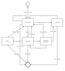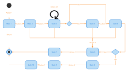


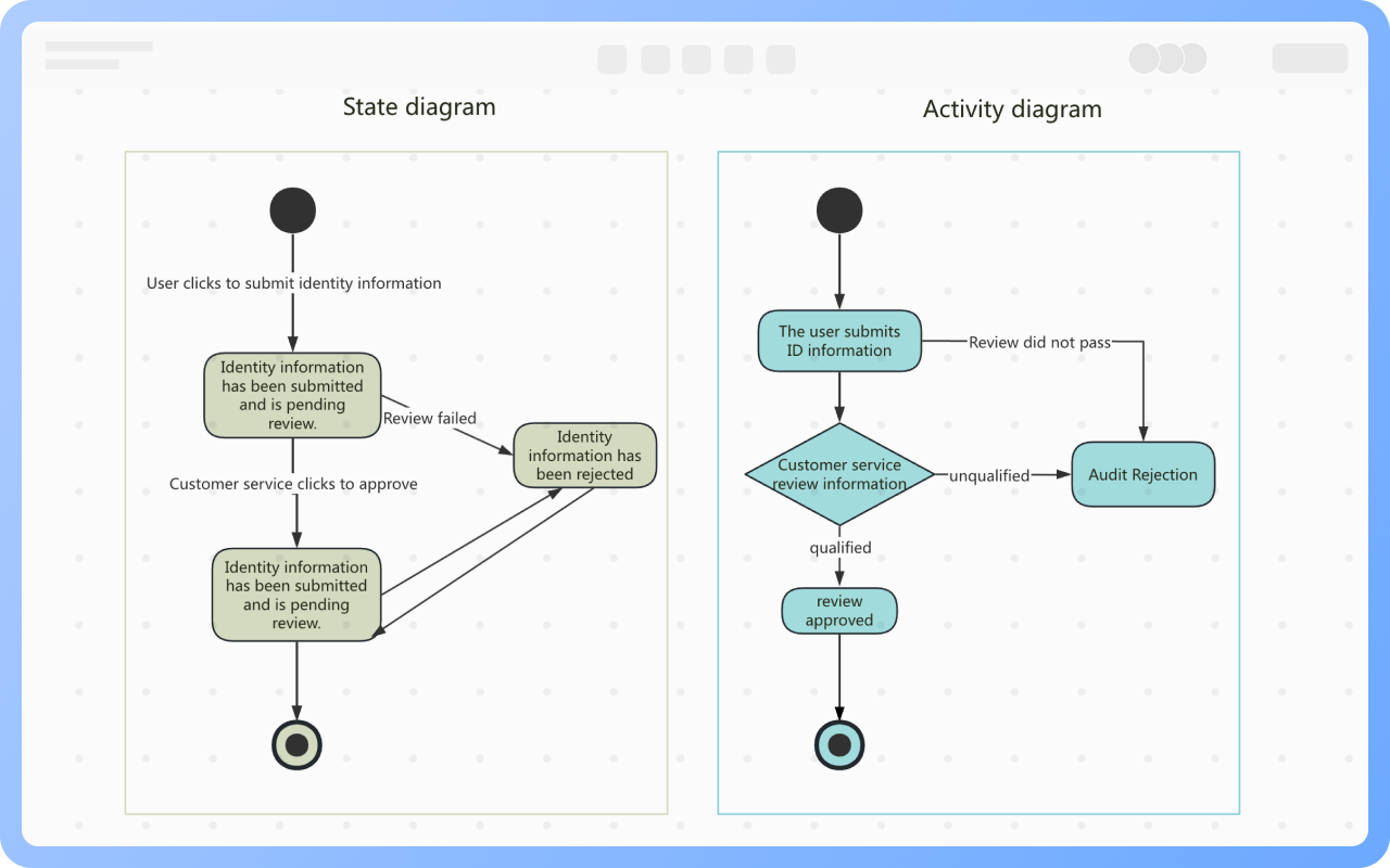
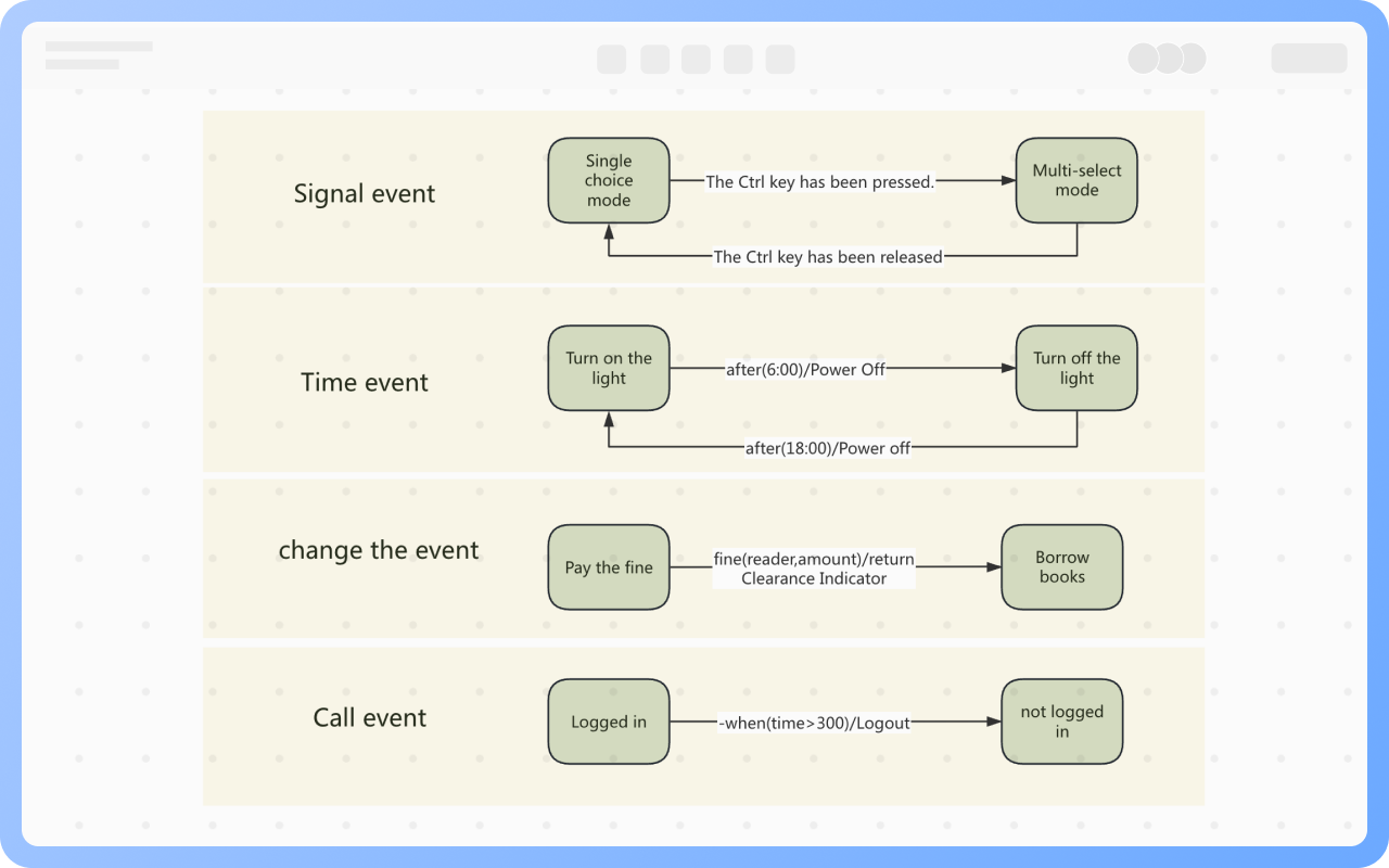
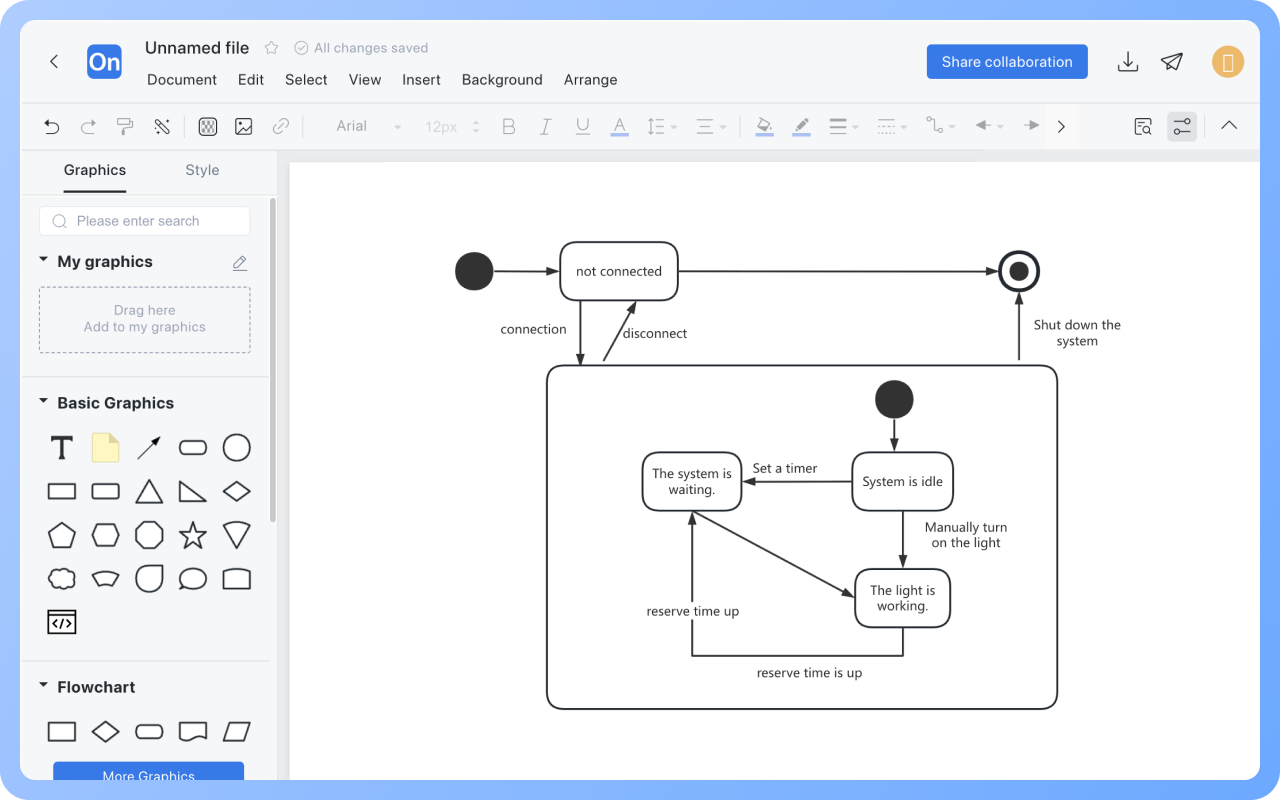
State diagrams express with a focus on states, rounded rectangles represent states, and the content written on the transition line corresponds to the activity in the activity diagram.
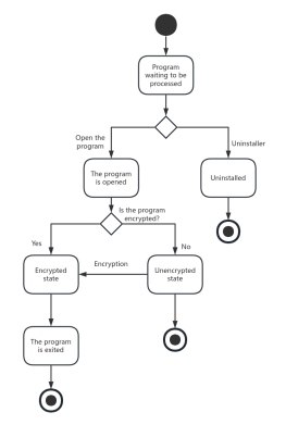
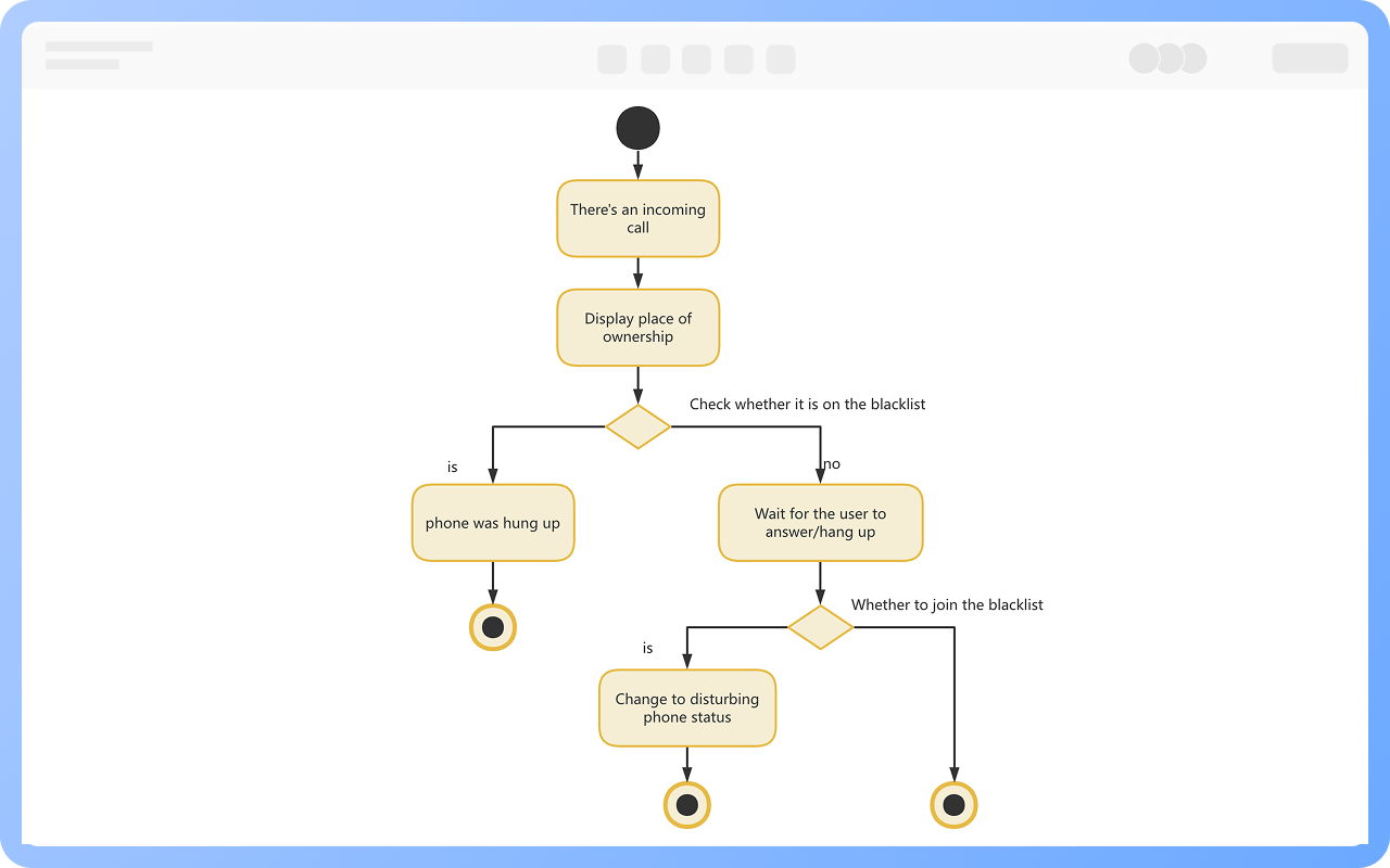
Activity diagrams express with a focus on activities, rounded rectangles represent activities, and content is usually not written on the transition line, except when making judgments, where the condition is written on the line.
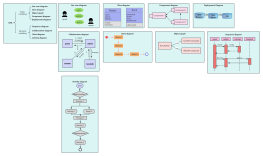
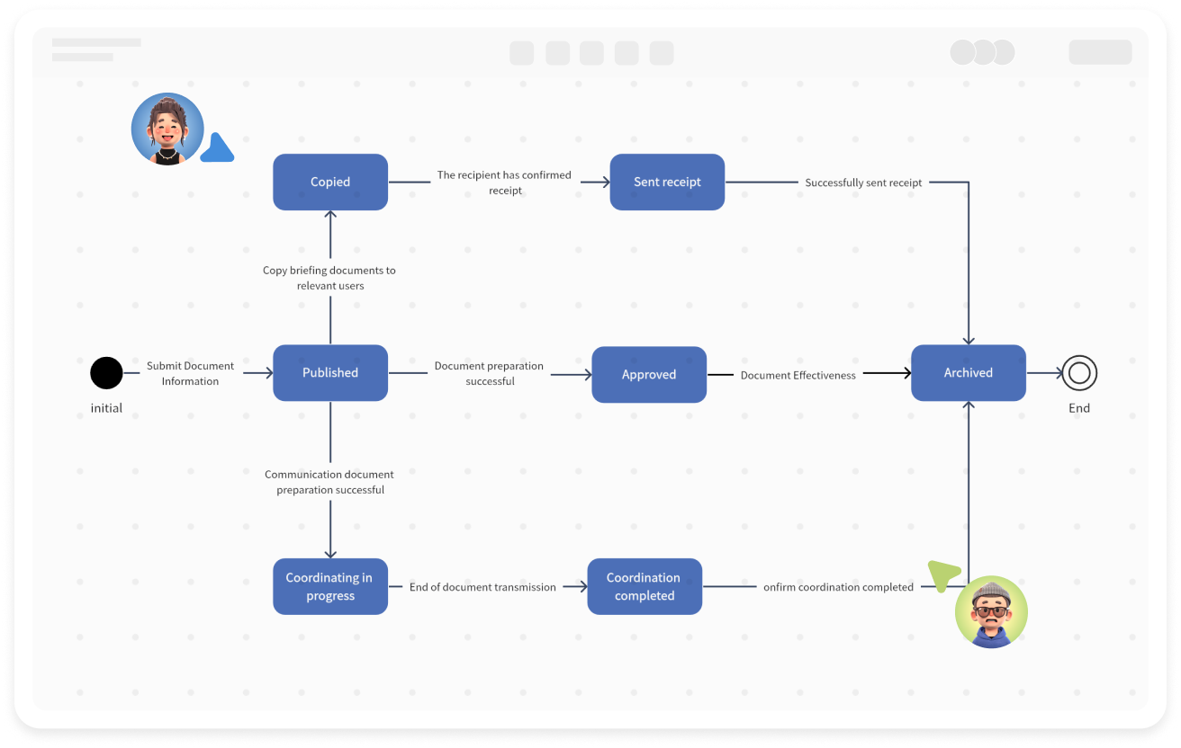
ProcessOn includes a comprehensive library of UML 2.5 state diagram symbols, encompassing various states, state transitions, trigger events, and more. Drag-and-drop operation is simple and efficient, with intelligent line snapping. It supports one-click alignment and batch spacing adjustment, allowing for quick layout even with complex UML state diagrams.
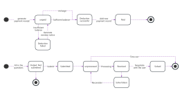
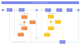
![[UML] Order processing state diagram](https://www.processon.io/chart_image/template/thumb/676911c4f4278a2300f90544.png?tid=6762a49e3415ee608db914cf)