Register
Process Type
Graphical expression
Mind Type
Structured expression
Note Type
Efficient expression

Class Diagram Generation Software

Free to use
Class Diagram Generation Software
What is Class Diagram

Class diagrams are a type of static view in UML modeling used to describe classes, interfaces, collaborations, and their relationships, showing the static structure of these concepts in a system. They are widely used in the system analysis and design phases of software engineering.

Class diagrams are a major component of object-oriented modeling and define the foundation for other UML diagrams. Based on class diagrams, state diagrams, collaboration diagrams, component diagrams, and configuration diagrams can be drawn.

Class diagrams are mainly used to display the static model of classes, interfaces, and their static structure and relationships within a system. Once a software designer designs a class diagram, programmers can implement the contents of the class diagram using code.

Free to use

ProcessOn Class Diagram Key Features

Online Collaboration

Supports real-time multi-user co-creation with shareable links for instant information transfer

Online Collaboration
One-Click AI Generation

Automatically generates graphics from text input and applies style enhancements

One-Click AI Generation
Personalized Style Customization

Prebuilt themes with full customization for personalized designs

Personalized Style Customization
Multiple Component Types

Supports icons, images, labels, LaTeX formulas, code blocks, links, attachments and more

Multiple Component Types
Multi-Format Compatibility

Export: PNG, VISIO, PDF, SVG | Import: VISIO, Mermaid

Multi-Format Compatibility
Cross-Device Sync

Real-time cloud storage, multi-device sync, version history, and secure data protection

Cross-Device Sync
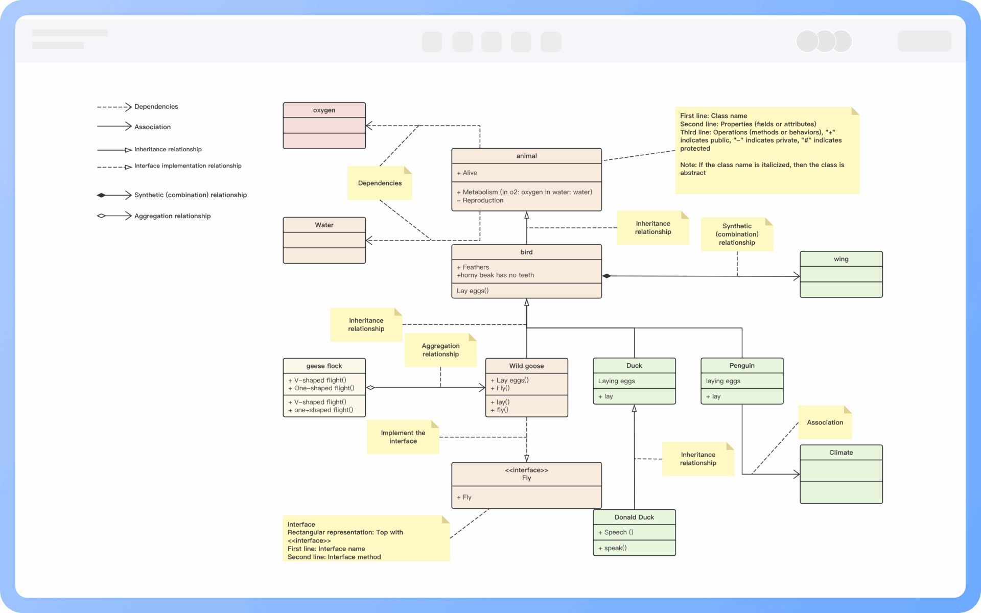
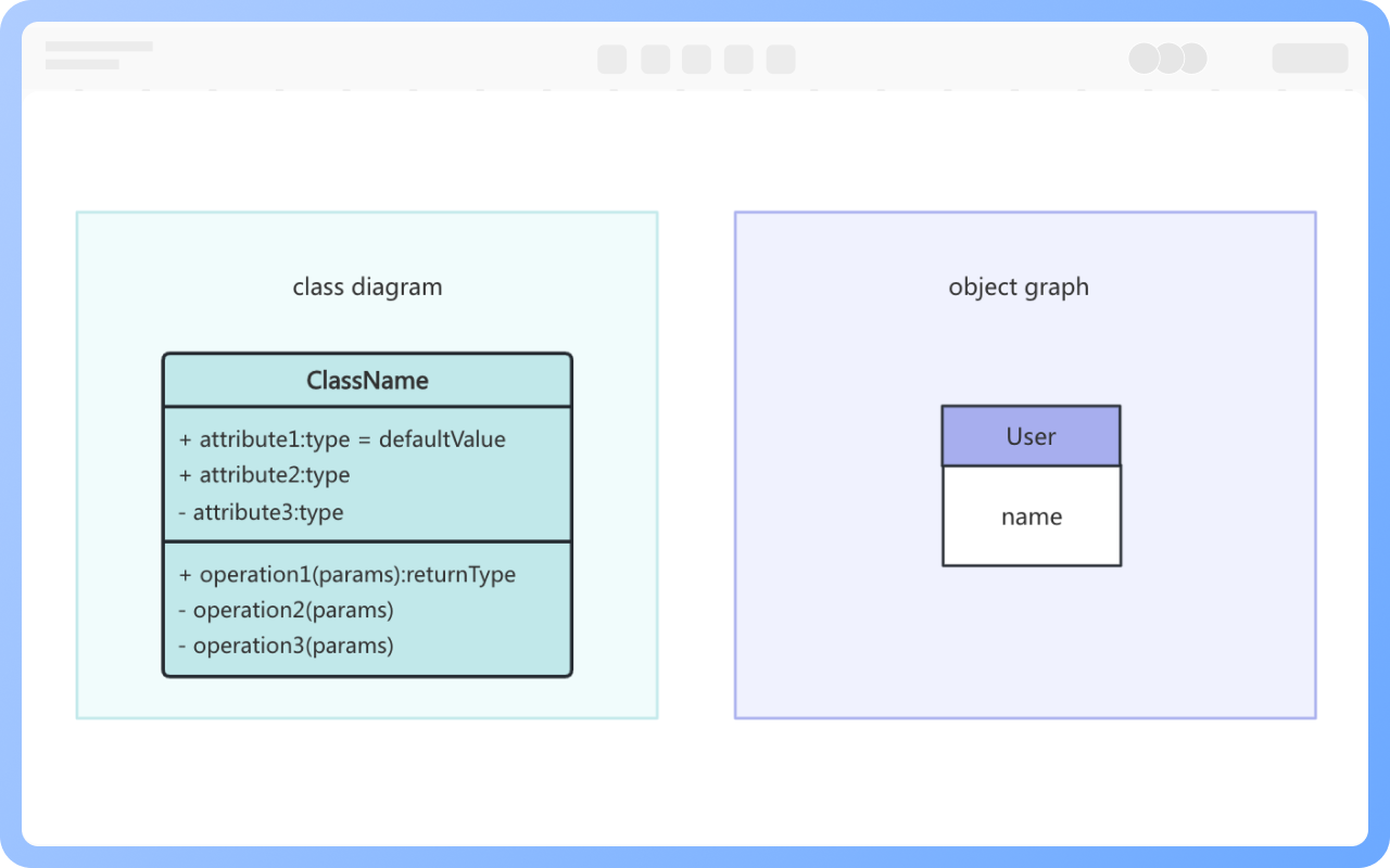
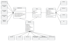
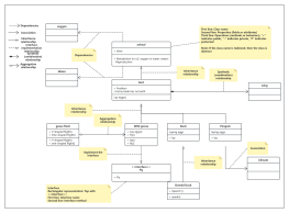
Class Diagram Composition

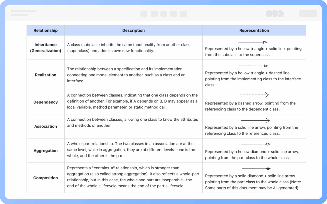
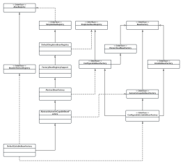
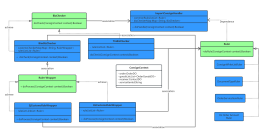
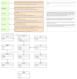
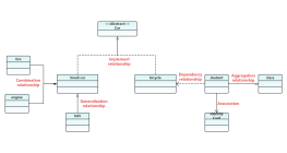
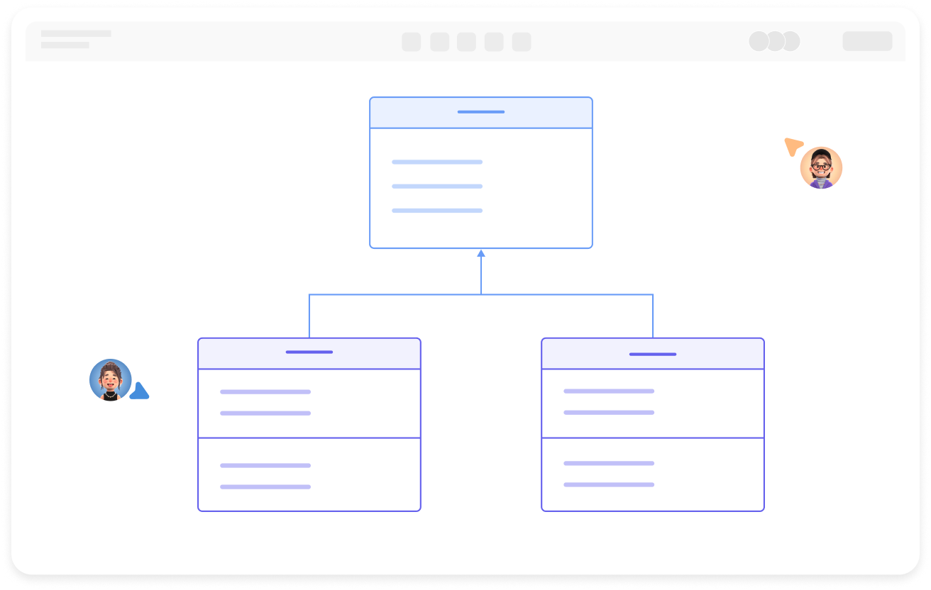
A class diagram primarily consists of classes, interfaces, and various relationships, mainly including generalization, dependency, association, and realization relationships.
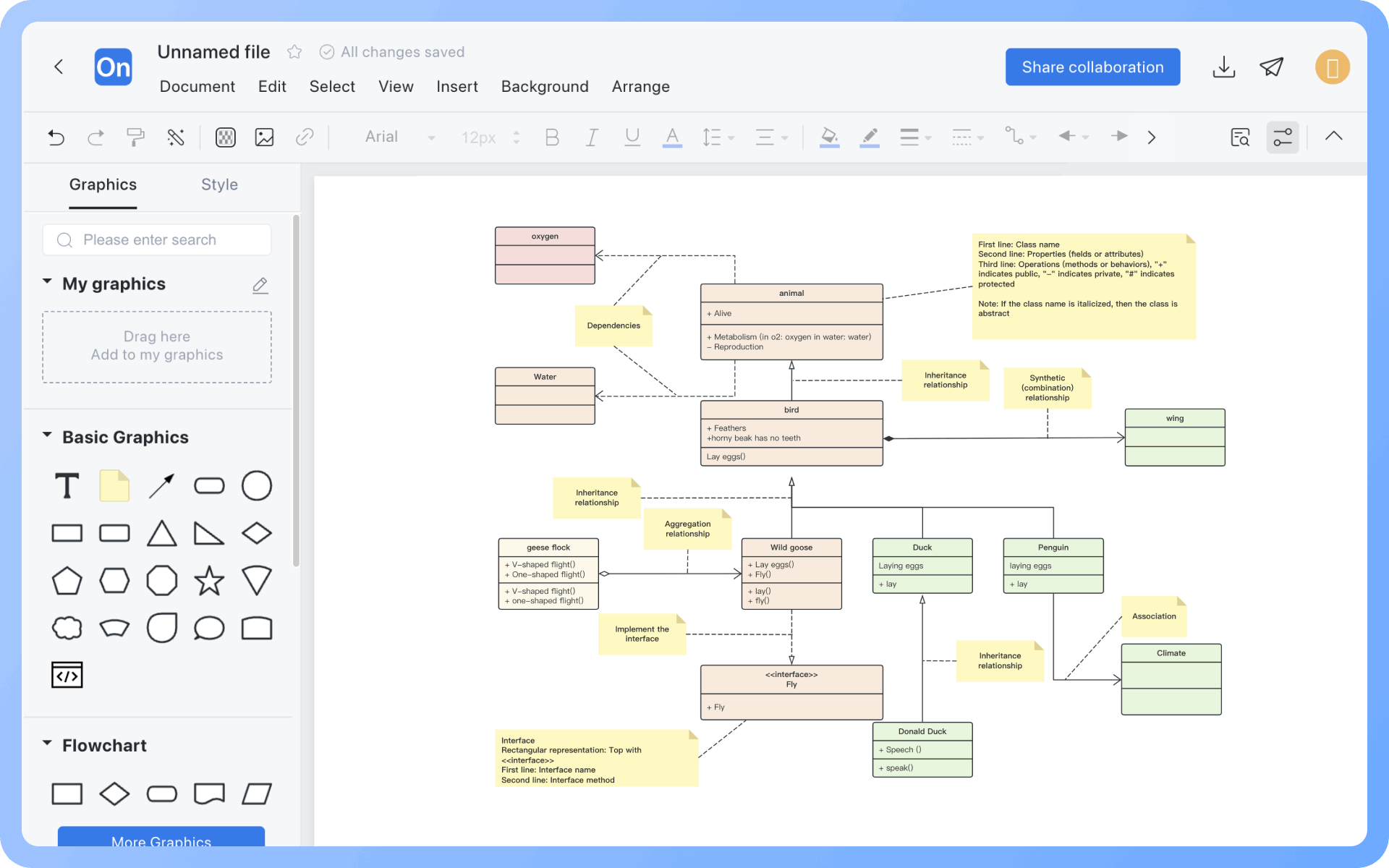
Create Charts Online
Class
Class Composition

A class typically consists of a name, attributes, and operations. In addition, class composition also includes the class's responsibilities, constraints, and annotations.

In a class diagram, a class is represented by a rectangular box divided into three layers: the first layer is the class name, the second layer is the class attributes, and the third layer is the class operations.

Create Charts Online
Class
Concrete and Abstract Classes

The name of a class should be a noun and should accurately and clearly reflect a concept in the problem domain. According to UML conventions, each word in the class name should start with a capital letter, using regular font to represent concrete classes and italic font to represent abstract classes.

Create Charts Online
Concrete
Interface Representation

Interfaces are also represented by rectangular boxes in class diagrams, but unlike classes, the top layer of an interface in a class diagram is marked with the stereotype <<interface>>, followed by the interface name, and the second layer contains the interface methods.

Create Charts Online
Interface
Relationships in Class Diagrams

There are certain relationships between classes and classes, classes and interfaces, and interfaces and interfaces. UML class diagrams usually have lines indicating these relationships. There are six types of relationships: realization, generalization, association, dependency, aggregation, and composition.

Create Charts Online
Relationships
Difference Between Class Diagrams and Object Diagrams

1. The model established by a class diagram describes a general situation, whereas the model established by an object diagram describes a specific situation.
2. A class diagram can completely describe the object structure of a system, whereas an object diagram cannot.
3. A class in a class diagram may correspond to multiple objects in an object diagram.

Create Charts Online
Difference

Class Diagram How to Draw?

Class DiagramHow to Draw?
1
Before starting to draw, it's necessary to sort out the classes, interfaces, and their relationships involved in the diagram
2
Create a 'UML Diagram', or first create a 'Flowchart', then add 'UML Class Diagram' symbols to the drawing area
3
Select the 'Class' icon from the left tool panel, drag it to the right drawing area, and label the class name, attributes, and methods
4
Select the 'Interface' icon from the left tool panel, drag it to the right drawing area, and label the interface name and methods
5
Use lines and arrows to label the relationships between classes, between classes and interfaces, and between interfaces
6
Check and confirm that the diagram is correct, and thus, a professional class diagram is completed
Free to use

Class Diagram Drawing Guide

  • How to create a UML class diagram? Rules, methods, examples

    How to create a UML class diagram? Rules, methods, examples

    UML class diagram graphically displays the classes in the system, their relationships, and the internal structure of the classes. These diagrams not only help developers understand the overall architecture of the system, but also promote communication and collaboration in teamwork, ensuring that all members have a common understanding of the design. This article will explain the concepts, rules, and drawing methods of class diagrams in detail, and share a large number of cases.
    Skye
    2024-10-25
    4027
  • UML diagram complete guide: Master 14 types of UML diagrams in 10 minutes

    UML diagram complete guide: Master 14 types of UML diagrams in 10 minutes

    This article uses the ProcessOn drawing tool to quickly and comprehensively explain what a UML diagram is? UML diagrams are divided into types and the conceptual uses of each diagram. Learn to use this tool efficiently to improve development efficiency and quality.
    Melody
    2025-03-03
    2409
  • A must-read for beginners: UML Introduction

    A must-read for beginners: UML Introduction

    UML (Unified Modeling Language) is a universal visual modeling language standard used to describe, visualize, construct and document software system artifacts. This article will explain UML from the perspective of its concept, meaning, and composition. Through this basic introduction, I believe that you will not only be able to deeply understand the historical context of UML, but also master its wide application in demand analysis, system design, and documentation.
    Skye
    2025-04-03
    743

Class Diagram Template Recommendations

More Templates

Class Diagram Frequently asked questions

Is the representation method of classes in class diagrams fixed?

Classes are usually composed of names, attributes, and operations, represented by a rectangular box divided into three layers: the first layer is the class name, the second layer is the class attributes, and the third layer is the class operations.
However, in practical use, there are three representations: "class name", "class name" + "class attributes", and "class name" + "class operations".

Can the name of a class be freely named?

The name of a class should be a noun, with the first letter of each word capitalized. Italic font is used for abstract classes, while regular font is used for instantiable classes.

How should the attributes of a class be represented?

The syntax for defining class attributes is: [visibility] attribute name [:data type] [=initial value] [{property string}]
The content in [] indicates optional elements.

What does class constraint mean?

Class constraints specify one or more rules that the class must satisfy. In UML, constraints are represented by text information enclosed in curly braces.

How should relationships in class diagrams be represented?

Implementation relationship: Represented by an open triangle + dashed line, pointing from the implementing class to the interface class.

Generalization relationship: Represented by an open triangle + solid line, pointing from the subclass to the parent class.

Association relationship: Represented by a solid line arrow, pointing from the referencing class to the referenced class.

Aggregation relationship: Represented by an open diamond + solid line, pointing from the part class to the whole class.

Composition relationship: Represented by a solid diamond + solid line, pointing from the part class to the whole class.

Dependency relationship: Represented by a dashed line arrow, pointing from the referencing class to the dependent class.

Are class diagrams completely independent?

Class diagrams are not completely independent. They should abstract entities, control, and boundary classes from use case diagrams and maintain semantic coordination with use case diagrams, activity diagrams, sequence diagrams, etc.

Can a class undertake multiple functions, or can multiple classes repeatedly define similar functions?

Classes should maintain a single responsibility. Large classes can be split, responsibilities reasonably distributed among multiple classes, avoiding high coupling, clarifying boundaries, and adhering to object-oriented design principles.

Related Diagrams