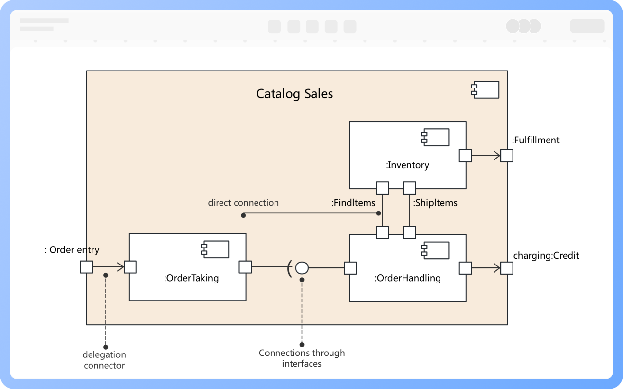
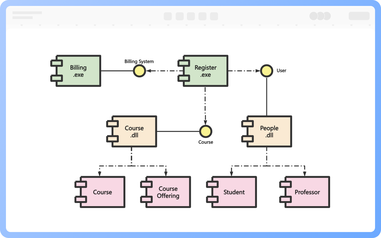
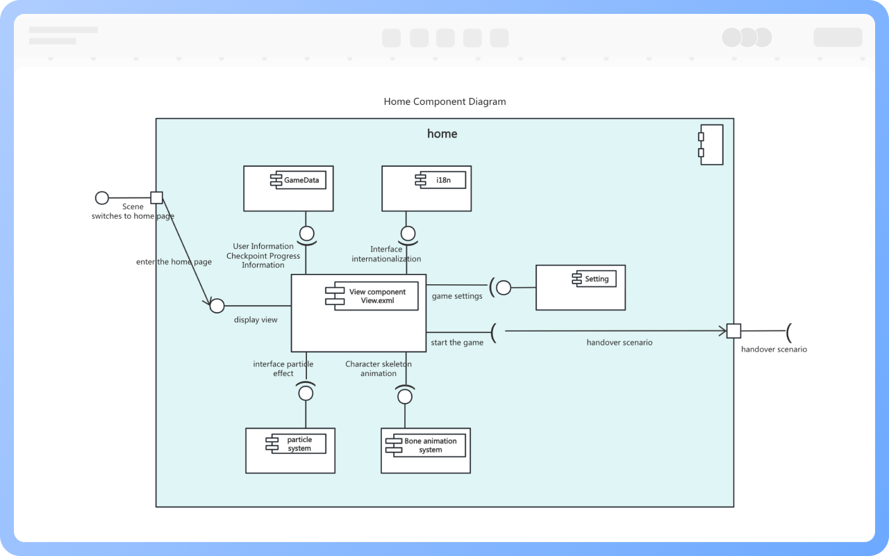
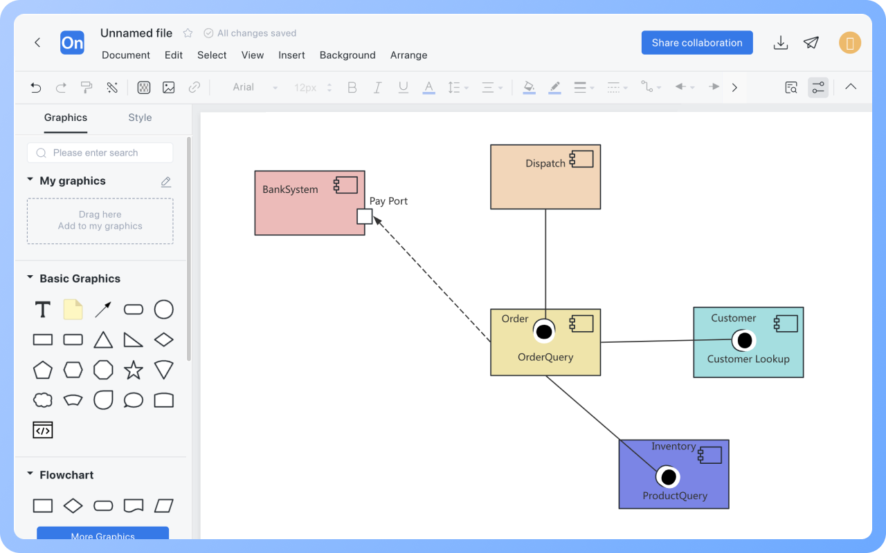
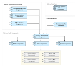
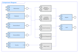
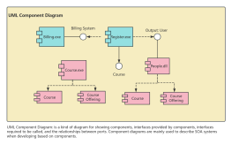
A component diagram illustrates the logical relationships between components.
A deployment diagram goes a step further by describing the physical topology of the system hardware and the software executing on that structure.
A component diagram, also known as an assembly diagram, is a model diagram used to represent the relationships between components and between components and interfaces in a system. Component diagrams are important in component-based system modeling and can help users understand the structure of the system.
Functions of the Component Diagram:
1. Allow system testers and developers to understand all the physical parts of the system as a whole;
2. Describe the main functions of a system from the perspective of software architecture;
3. Facilitate project team members' understanding of the system's structure and functions;
4. Contribute to software reuse.
Supports real-time multi-user co-creation with shareable links for instant information transfer
Automatically generates graphics from text input and applies style enhancements
Prebuilt themes with full customization for personalized designs
Supports icons, images, labels, LaTeX formulas, code blocks, links, attachments and more
Export: PNG, VISIO, PDF, SVG | Import: VISIO, Mermaid
Real-time cloud storage, multi-device sync, version history, and secure data protection
A component diagram illustrates the logical relationships between components.
A deployment diagram goes a step further by describing the physical topology of the system hardware and the software executing on that structure.
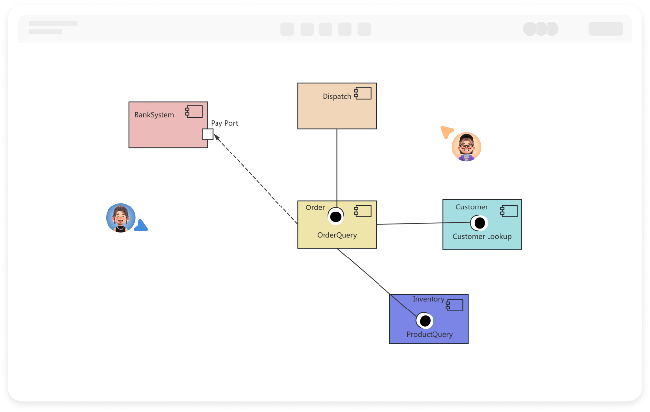
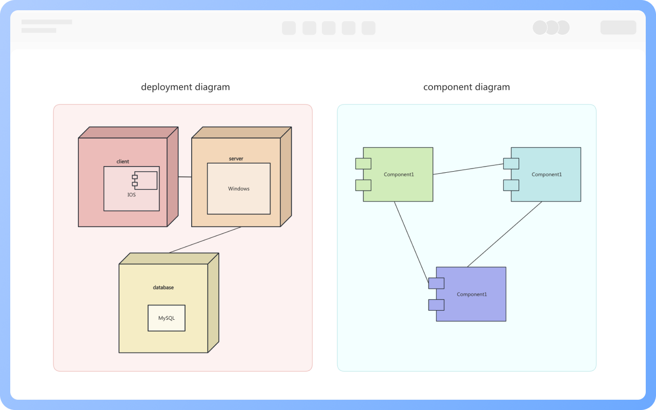
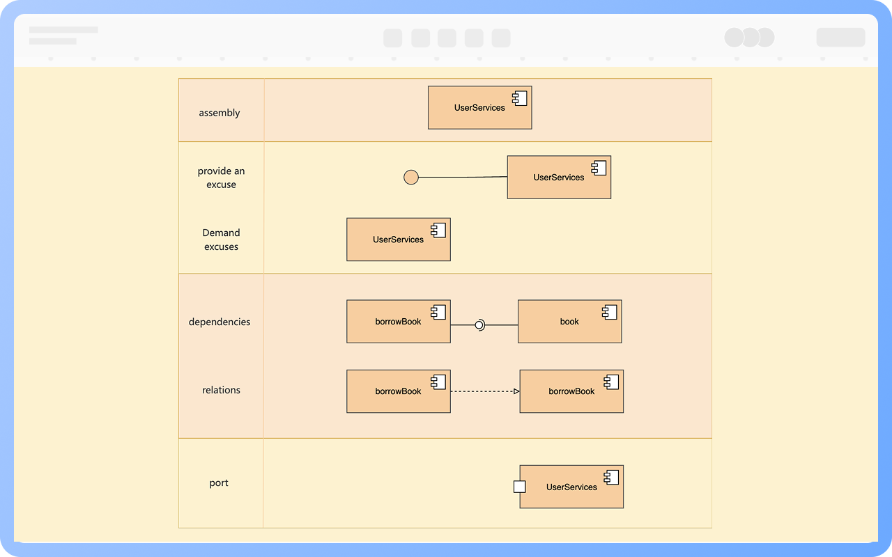
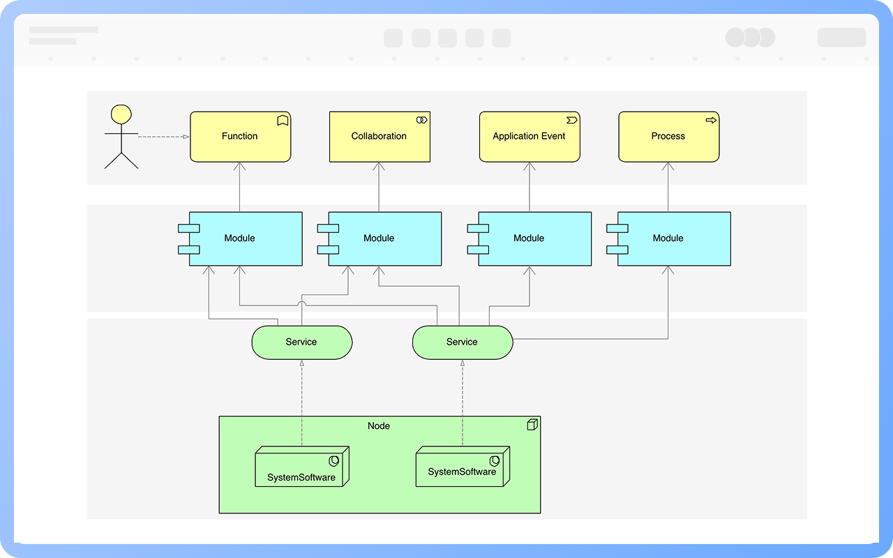
Component: A component is a well-defined, replaceable physical implementation unit, generally representing an existing physical object, depicted as a rectangle with two small protruding rectangles on the left side.
Interface: A provided interface, also known as an exported interface, is the collection of services offered by a component, represented by the realization relationship between the interface and the component; a required interface, also known as an imported interface, is the interface followed by a component when requesting corresponding services from other components, represented by a dependency relationship.
Relationship: Between components --> dependency relationship, if there is a generalization or usage relationship between classes in two components, a dependency can be added; between component and interface --> dependency or realization.
Simple Component Diagram: Organizes classes that collaborate with each other into a component.
Nested Component Diagram: Uses nested component diagrams to represent the internal structure of a component.
Components are connected through ports, and ports are connected through connectors, although they are generally not commonly used.
Connectors are divided into direct connectors, interface connectors, and delegation connectors.
1. Collaborative development by multiple teams
2. Microservices or modular architecture
3. Systems with clear interface constraints
4. Components requiring separate deployment (e.g., frontend, backend, database)
1. Focus on modularization and decoupling, as the main value of component diagrams is to clearly display system layering and dependencies;
2. Use standard symbols and interface annotations to enhance the readability and consistency of the diagram;
3. Use in conjunction with class diagrams/deployment diagrams to provide a complete view of structure, behavior, and deployment;
4. Avoid drawing component diagrams as class diagrams, as component diagrams express system 'structure' rather than 'implementation details'.
Component diagrams answer 'who does what, who depends on whom', while class diagrams answer 'how to do it'.
1. Classes represent an abstraction of entities, while components represent an abstraction of physical parts existing in a computer.
2. Components belong to software modules rather than logical modules, and compared to classes, they are at different levels of abstraction.
3. Classes can directly have operations and attributes, while components only have operations accessible through their interfaces.
Components are classified into three types based on their role in the system:
1. Deployment components: Necessary components to form an executable system.
For example, Java Virtual Machine, Database Management System, EXE files, DLL files.
2. Work product components: Intermediate products of the development process, not directly involved in the executable system.
For example, source code files, data files.
3. Execution components: Components created at runtime.
For example, instantiated Servlets, COM+ objects, XML documents.
Component to component: Dependency relationship
Component to interface: Dependency or implementation relationship
To control appropriate component granularity, generally, functional modules can be set as components; do not design a single class as a component.
Drag 'interface' from the symbol area on the left to the work area on the right, then click one end of the component, hold down the left mouse button to the corresponding interface, release the mouse to specify the interface the component needs to implement.
No, simple components can have no explicit interfaces.
Provided interface, represented by a circle, refers to the functions exposed by this component (can be called).
Required interface, represented by a semicircle, refers to the services this component relies on from other components.
Yes. There can be one-to-many dependencies, bidirectional dependencies, or decoupling through mediator components between components, using multiple dashed lines to represent multiple dependency relationships.