Register
Process Type
Graphical expression
Mind Type
Structured expression
Note Type
Efficient expression

UML Deployment Diagram Software

Free to use
UML Deployment Diagram Software
What is Deployment Diagram

Deployment diagrams, also known as implementation diagrams or configuration diagrams, are a type of static diagram in UML used to model the physical structure of a system, describing the physical topology of hardware in the system and the software executed on this structure.

Like component diagrams, deployment diagrams are one of the two types of diagrams for modeling the physical structure of object-oriented systems.

A system model has only one deployment diagram, which is typically used to help understand distributed systems and is prepared during the implementation phase of the development process. It shows the physical layout of nodes in a distributed system, the artifacts stored on each node, and the components and other elements realized by the artifacts.

Free to use

ProcessOn Deployment Diagram Key Features

Online Collaboration

Supports real-time multi-user co-creation with shareable links for instant information transfer

Online Collaboration
One-Click AI Generation

Automatically generates graphics from text input and applies style enhancements

One-Click AI Generation
Personalized Style Customization

Prebuilt themes with full customization for personalized designs

Personalized Style Customization
Multiple Component Types

Supports icons, images, labels, LaTeX formulas, code blocks, links, attachments and more

Multiple Component Types
Multi-Format Compatibility

Export: PNG, VISIO, PDF, SVG | Import: VISIO, Mermaid

Multi-Format Compatibility
Cross-Device Sync

Real-time cloud storage, multi-device sync, version history, and secure data protection

Cross-Device Sync
Difference between Deployment Diagram and Component Diagram

The component diagram illustrates the logical relationships between components.

The deployment diagram goes a step further by describing the physical topology of the system hardware and the software that executes on this structure.

Create Charts Online
Difference
Elements of Deployment Diagram

Nodes and Node Instances

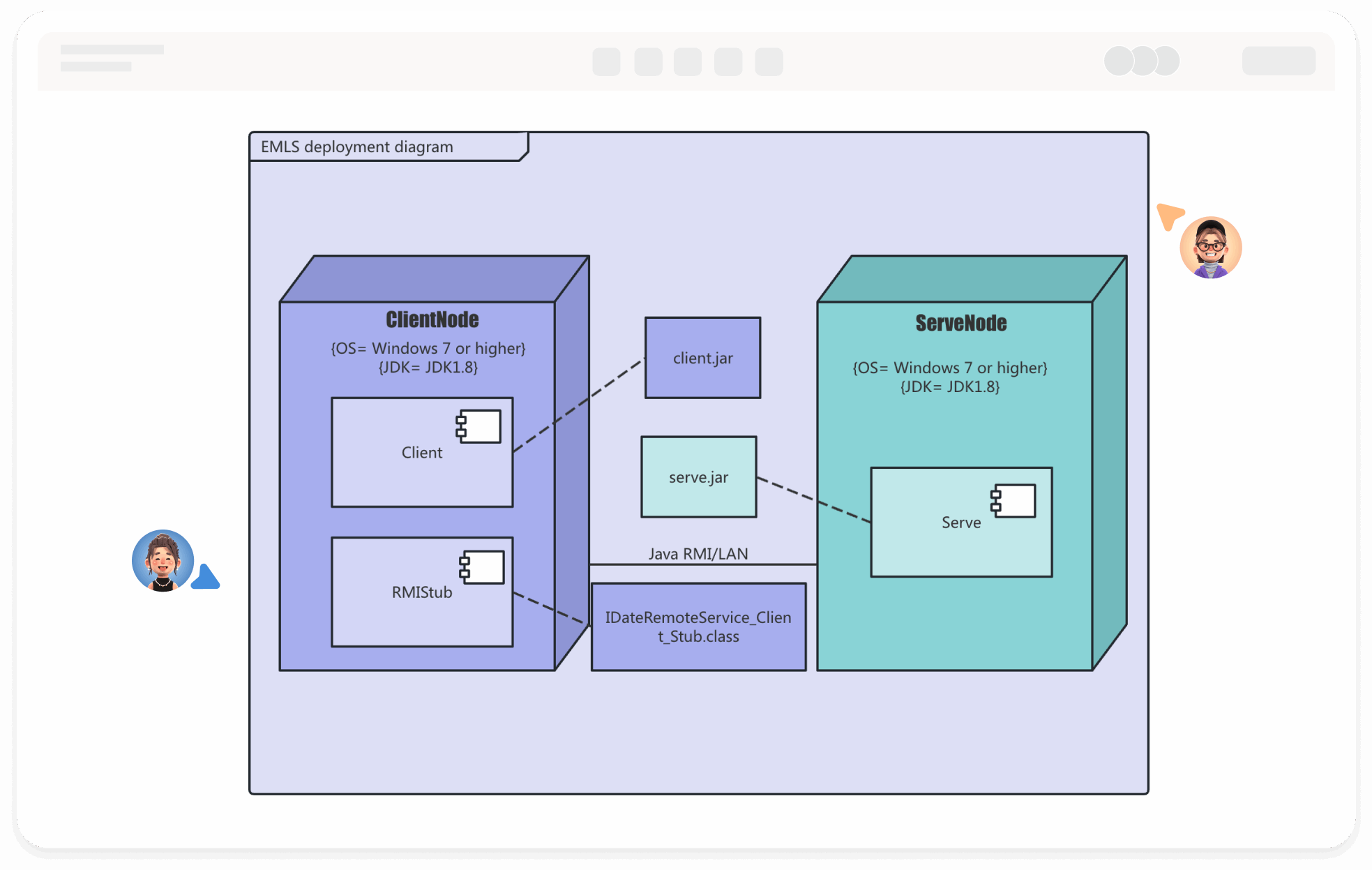
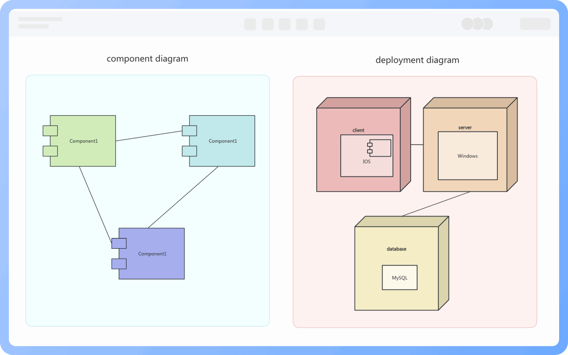
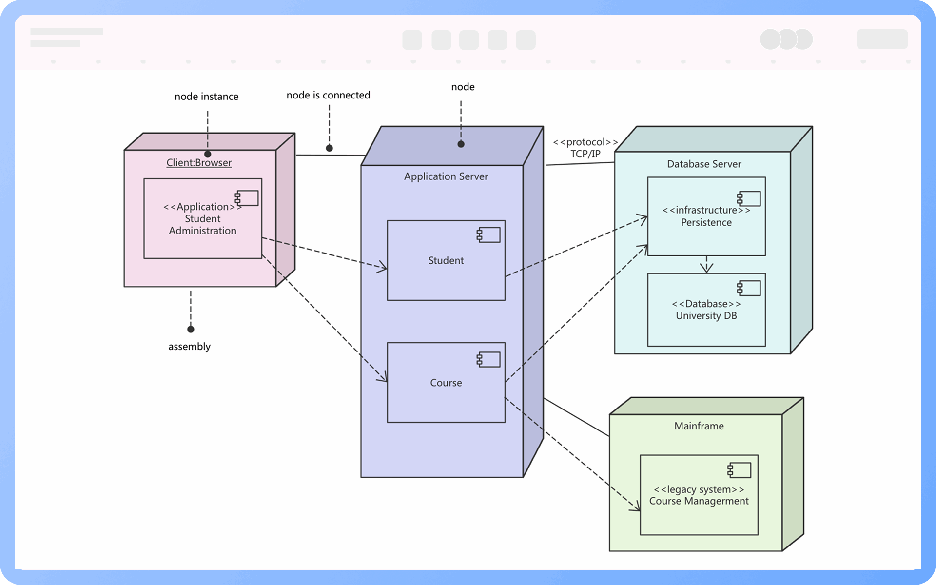
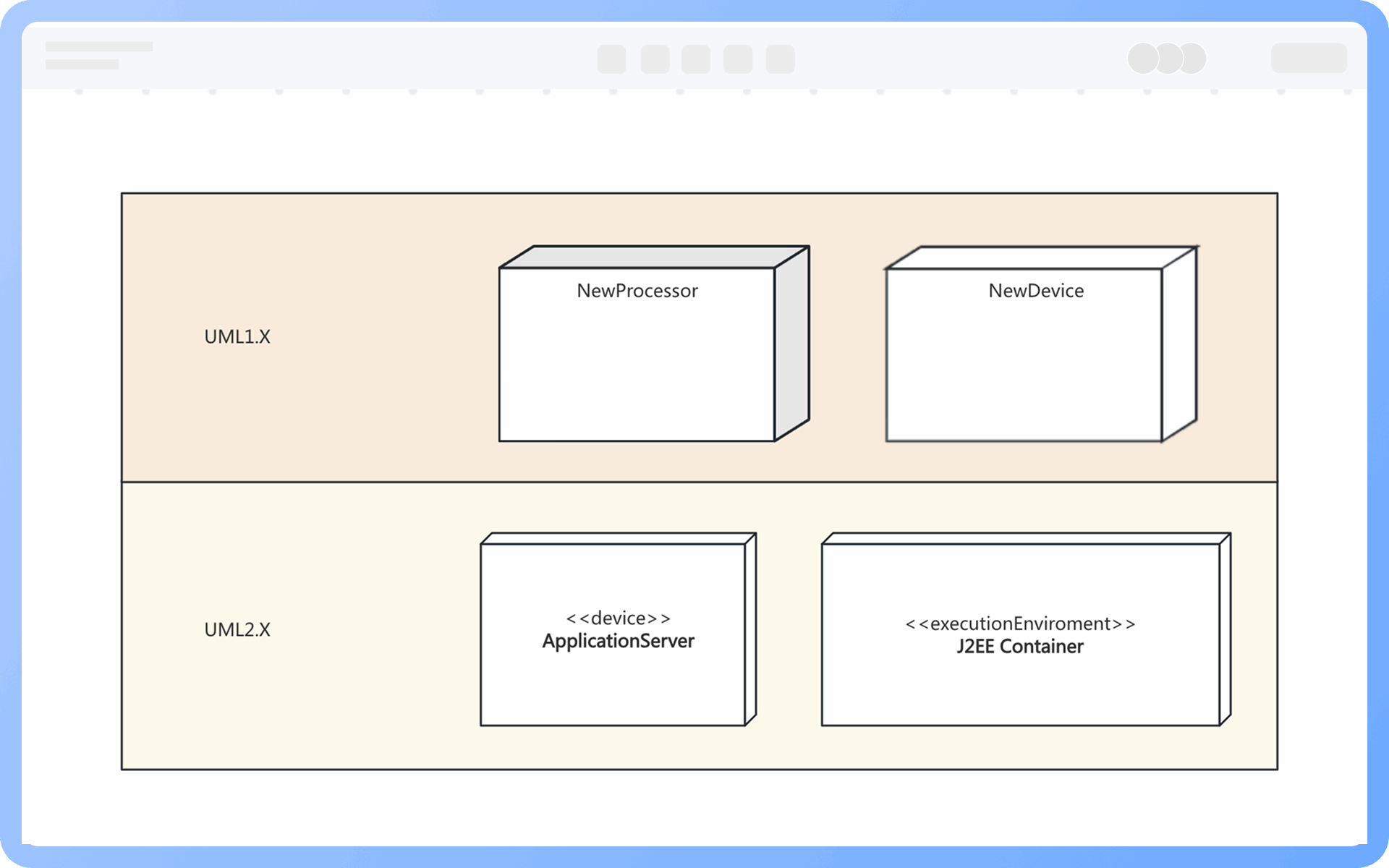
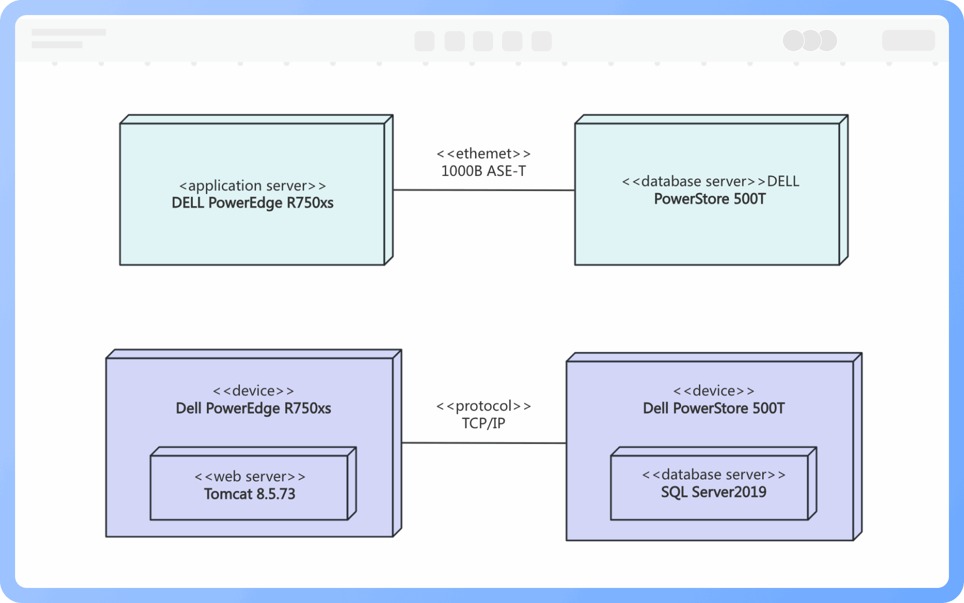
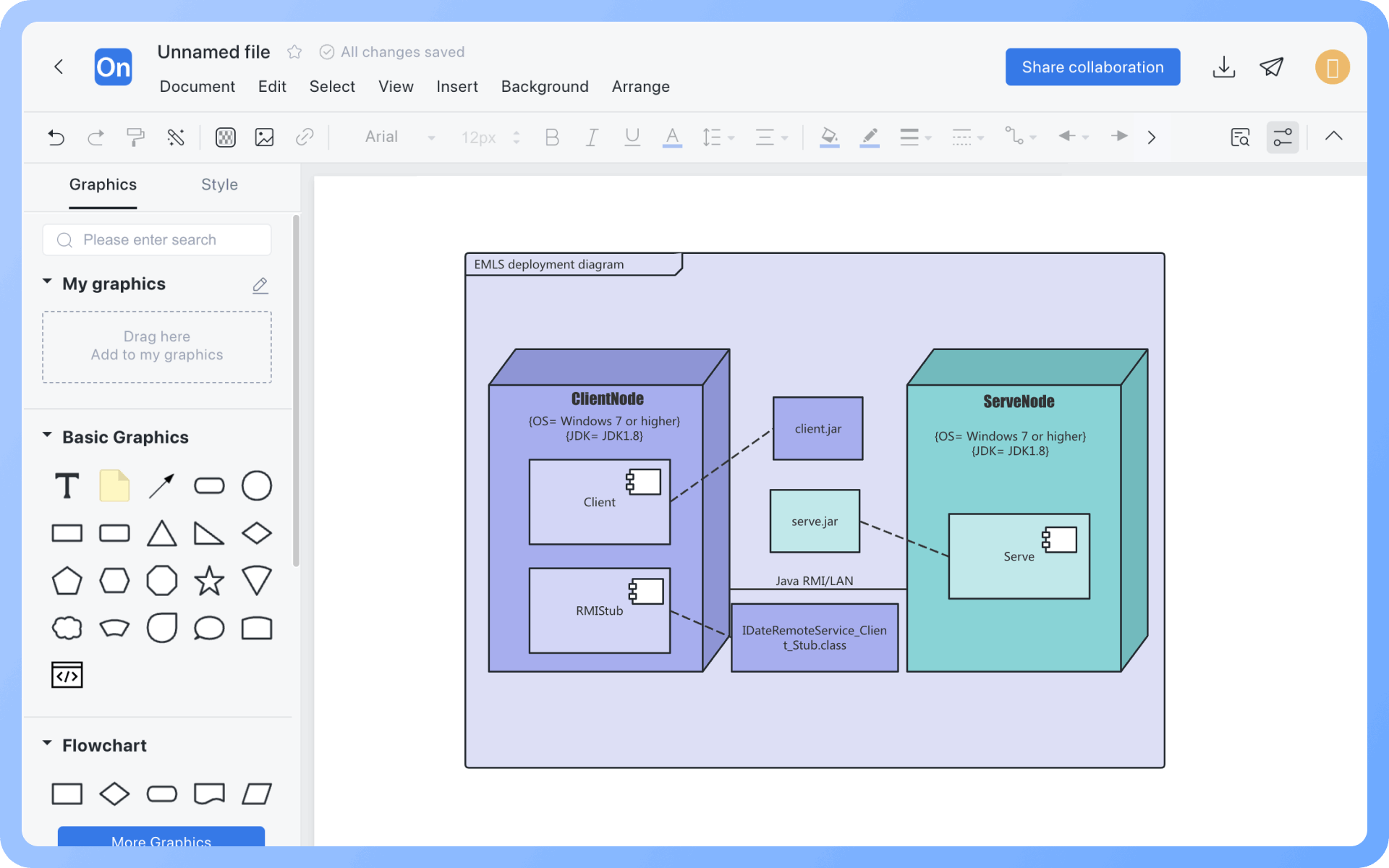
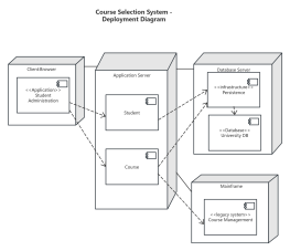
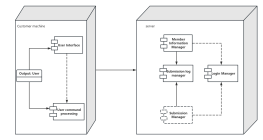
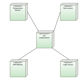
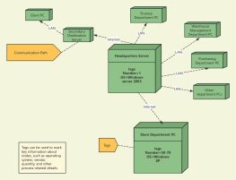
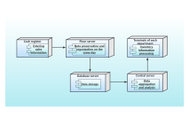
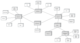
1. Nodes are model elements used to represent the computing resources of a system, typically the hardware or the runtime environment, represented as cubes.

2. Node instances are based on existing nodes, with the instance name underlined, and a colon before the node type.

Components and Component Instances

1. Components are the products of the software development process, including process models (such as use case diagrams, design diagrams), source code, executable programs, design documents, test reports, requirement prototypes, user manuals, etc.

2. Component instances are based on existing components, with the instance name underlined, and a colon before the component type.

Node Connections

Node connections refer to the lines between nodes, representing the communication paths for interaction between systems.

Create Charts Online
Elements
Node Classification

In UML1.x, nodes are divided into processor nodes and device nodes. Processors are represented as shaded cubes, while devices are unshaded cubes.

In UML2.x, nodes are divided into device nodes and execution environments. Devices are represented using cubes with the <

Create Charts Online
Node
Relationships between Nodes

When the deployment target is a physical device, the communication path usually represents the physical connection between two nodes.

When the two deployment targets are execution environment nodes, the communication path is typically some protocol.

Create Charts Online
Relationships
Purpose of Deployment Diagram

1. Describe the deployment structure, showing where services, databases, web applications, etc., are deployed on servers, nodes, or containers;
2. Display node communication relationships, expressing connections, message interactions, and call paths between servers;
3. Support system deployment planning, helping developers and operations personnel clearly understand the actual operating structure of the system;
4. Support operations and system documentation, useful for designing deployment manuals, system description documents, DevOps guidance files, etc.

Create Charts Online
Purpose
Extension of Deployment Diagram

Deployment diagrams, network topology diagrams, and deployment architecture diagrams have many similarities and can easily be confused. Here's a one-sentence summary of the differences between these three types of diagrams:

Deployment diagrams are used to model how software components are deployed in the runtime environment, suitable for system engineers and architects;
Network topology diagrams are used to display physical or logical network structures, suitable for network engineers/IT operations;
Deployment architecture diagrams are used to describe the actual deployment structure of systems or platforms, suitable for technical presentations, DevOps teams.

Create Charts Online
Extension

Deployment Diagram How to Draw?

Deployment DiagramHow to Draw?
1
Before starting to draw a deployment diagram, identify components (list all software systems and hardware devices), clarify relationships (figure out how these parts are connected and work together), and gather requirements (collect detailed information about hardware devices, network settings, and any special rules)
2
Create a 'UML Diagram', or first create a 'Flowchart', then add 'UML Deployment Diagram' symbols to the drawing area
3
Draw nodes and components: First, use standard symbols to roughly draw hardware devices (nodes) and software parts (components), and name them correctly
4
Connect nodes and components: Use lines or arrows to show how nodes and components are connected, indicating how they communicate with each other
5
Add details: Clearly label everything and include any additional information, such as hardware specifications or communication protocols
6
Check and confirm the diagram is correct, and thus, a professional activity diagram is completed
Free to use

Deployment Diagram Drawing Guide

  • What is UML

    What is UML "Deployment Diagram"? Tutorial and Examples

    UML , or Unified Modeling Language , is a visual modeling language used for software system analysis and design. UML diagrams are mainly divided into structural behavior diagrams and dynamic behavior diagrams. This article will share the concepts, elements, and drawing tutorials of deployment diagrams in structural UML diagrams, and share application cases.
    ProcessOn-Ares
    2024-11-26
    1939
  • UML diagram complete guide: Master 14 types of UML diagrams in 10 minutes

    UML diagram complete guide: Master 14 types of UML diagrams in 10 minutes

    This article uses the ProcessOn drawing tool to quickly and comprehensively explain what a UML diagram is? UML diagrams are divided into types and the conceptual uses of each diagram. Learn to use this tool efficiently to improve development efficiency and quality.
    Melody
    2025-03-03
    2409
  • A must-read for beginners: UML Introduction

    A must-read for beginners: UML Introduction

    UML (Unified Modeling Language) is a universal visual modeling language standard used to describe, visualize, construct and document software system artifacts. This article will explain UML from the perspective of its concept, meaning, and composition. Through this basic introduction, I believe that you will not only be able to deeply understand the historical context of UML, but also master its wide application in demand analysis, system design, and documentation.
    Skye
    2025-04-03
    743

Deployment Diagram Template Recommendations

More Templates

Deployment Diagram Frequently asked questions

How to distinguish between processor nodes and device nodes?

In UML1.x, nodes are divided into processor nodes and device nodes. Processor nodes are represented by shaded cubes, while device nodes are represented by unshaded cubes.

What is the difference between a node and a node instance?

A node instance is based on an existing node. The name of a node instance will have an underline, and there will be a colon before the node type.

What is the difference between a component and a component instance?

A component instance is based on an existing component. The name of a component instance will have an underline, and there will be a colon before the component type.

What does the dashed line in a deployment diagram mean?

The dashed line in a deployment diagram usually represents the relationship or dependency between elements, indicating that one element is related to or depends on another element.

Can deployment diagrams represent concurrency or load balancing?

Yes, deployment diagrams use multiple nodes to represent clusters or redundant deployments, adding annotations such as "load balancing" or "primary-backup."
Deployment diagrams do not focus on detailed operational mechanisms but can provide an understanding of the overall structure.

Must deployment diagrams include components?

Not necessarily. Simple deployment diagrams can just show nodes and their connections.

Can deployment diagrams depict network communication relationships?

Yes, primarily at a high-level logic. Communication between nodes can be represented with labeled connections, indicating communication protocols (e.g., HTTP, RPC, TCP).
However, it is not recommended to use deployment diagrams to detail network topology; complex networks are better supplemented with network architecture diagrams.

Related Diagrams