Register
Process Type
Graphical expression
Mind Type
Structured expression
Note Type
Efficient expression

Collaboration Diagram Online Drawing

Free to use
Collaboration Diagram Online Drawing
What is Collaboration Diagram

The collaboration diagram, also known as the communication diagram, is a type of UML interaction diagram that shows the collaboration between objects due to system events described in use cases, focusing on the cooperative relationships between objects. The collaboration diagram emphasizes how objects are linked and what messages are passed between them during specific interactions.

The collaboration diagram is mainly composed of three elements: objects, messages, and links. By establishing links between objects and adding messages to the links, it indicates the interaction between objects, and the message names reflect the intent of the referencing objects.

Since UML 2.0, collaboration diagrams have been replaced by communication diagrams, which are uniformly referred to as communication diagrams in the following text.

Free to use

ProcessOn Collaboration Diagram Key Features

Online Collaboration

Supports real-time multi-user co-creation with shareable links for instant information transfer

Online Collaboration
One-Click AI Generation

Automatically generates graphics from text input and applies style enhancements

One-Click AI Generation
Personalized Style Customization

Prebuilt themes with full customization for personalized designs

Personalized Style Customization
Multiple Component Types

Supports icons, images, labels, LaTeX formulas, code blocks, links, attachments and more

Multiple Component Types
Multi-Format Compatibility

Export: PNG, VISIO, PDF, SVG | Import: VISIO, Mermaid

Multi-Format Compatibility
Cross-Device Sync

Real-time cloud storage, multi-device sync, version history, and secure data protection

Cross-Device Sync
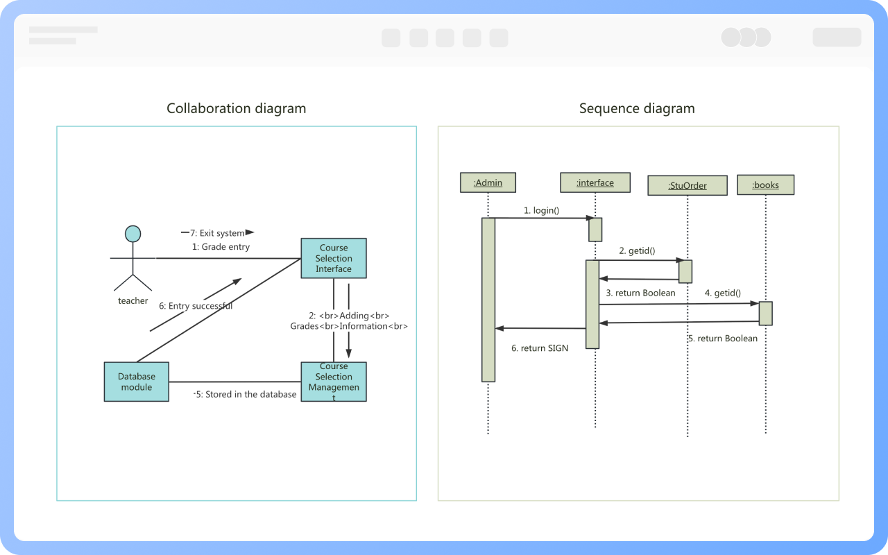
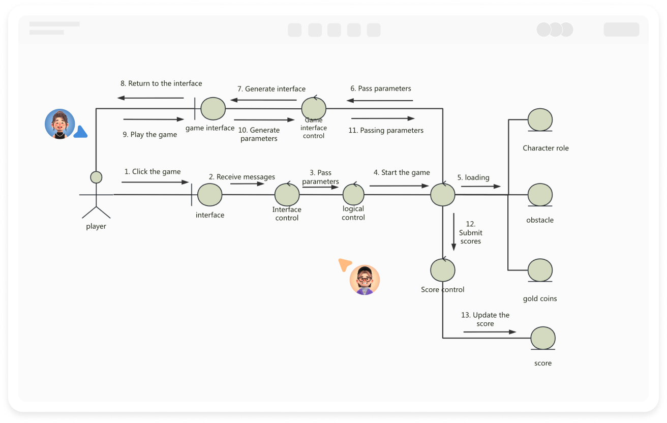
Comparison of Communication Diagram and Sequence Diagram

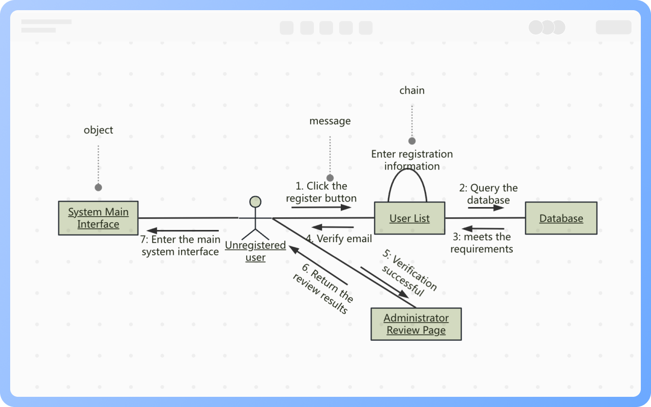
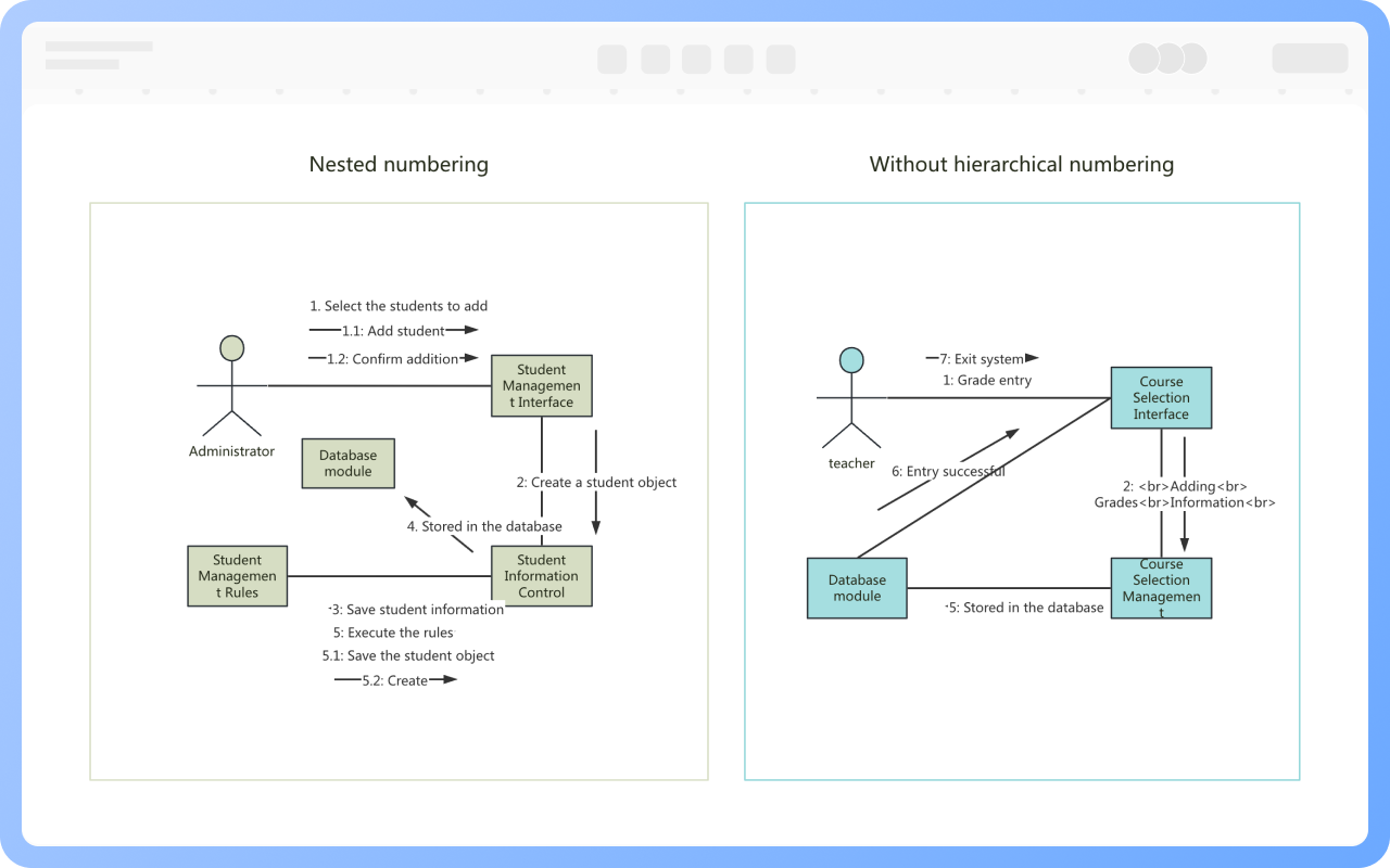
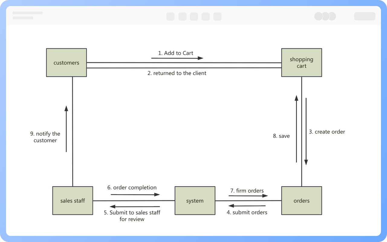
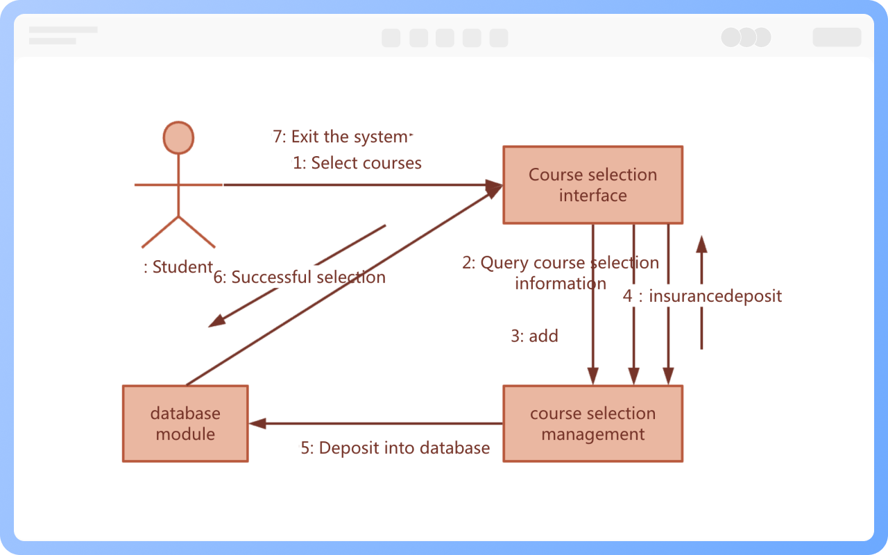
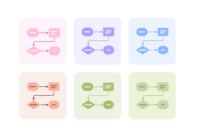
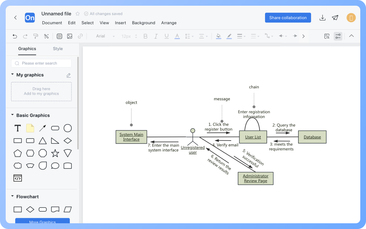
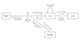
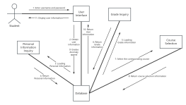
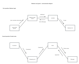
Communication diagrams and sequence diagrams are both UML interaction diagrams, which can be transformed into each other, have similar responsibilities, are message-driven, and have sequentiality.
However, there are also obvious differences. Communication diagrams express the cooperation relationship between objects, while sequence diagrams express the time sequence of messages occurring between objects.

Create Charts Online
Comparison
Elements of Communication Diagram

Communication diagrams are mainly composed of objects, messages, and links.

Object: The concept of objects in collaboration diagrams and sequence diagrams is the same, but in collaboration diagrams, the creation and destruction of objects cannot be represented, so there are no restrictions on the position of objects in the diagram.

Message: A message consists of a sender, a receiver, and a message name. To indicate the sending order of messages during the interaction process, a sequence number needs to be added to the message.

Link: A link is the connection between objects and is an instance of class association. Links use solid lines or arcs to connect two objects.

Create Charts Online
Elements
Message Classification

Messages are generally divided into synchronous messages, asynchronous messages, return messages, and self-associated messages.

Synchronous Message: After sending a message, the object needs to wait for the receiving object to respond and return the message before proceeding with other work, represented by a "solid line arrow";

Asynchronous Message: After sending a message, the object does not need to wait for the return message from the receiving object and can continue executing other work, represented by a "solid line + greater than sign";

Return Message: Returns from a process call, represented by a "dashed line arrow";

Self-associated Message: Represents a method's self-call or a call from one method to another within the same object, represented by a "semi-closed rectangle + solid line arrow below".

Create Charts Online
Message
Message Numbering

There are two types of message numbering: one is non-hierarchical numbering (sequential numbering), which is simple and intuitive; the other is nested numbering, which is easier to represent the containment relationship of messages.

Create Charts Online
Message
Modeling Sequence of Communication Diagram

1. Set the context of the interaction

2. Set the scene of the interaction

3. Set initial characteristics for each object

4. Describe the links along which information may be transmitted between objects

5. Set the sequence number of messages

Create Charts Online
Modeling
Purpose of Communication Diagram

For Use Cases: Reflects the logical expression of the specific usage context by describing the transmission of messages between objects

For Objects: Shows the spatial organizational structure of objects and their interaction relationships

For Classes: Demonstrates the implementation of a class operation

Create Charts Online
Purpose

Collaboration Diagram How to Draw?

Collaboration DiagramHow to Draw?
1
Before starting to draw the communication diagram, it is necessary to sort out all the objects to avoid omissions
2
Create a 'UML diagram' from the personal file page, drag the graphic symbols on the left to the drawing area to add as objects, and name the objects
3
Draw the links between objects, drag lines to the drawing area based on the interaction between objects to connect them
4
Add messages, drag text onto the links where messages need to be added, and enter the message name and number
5
Adjust the layout of objects, optimize the arrangement of messages, beautify the graphic style to make reading easier
6
Check and confirm the diagram is correct, and thus, a professional collaboration diagram is completed
Free to use

Collaboration Diagram Drawing Guide

  • A must-read for beginners: UML Introduction

    A must-read for beginners: UML Introduction

    UML (Unified Modeling Language) is a universal visual modeling language standard used to describe, visualize, construct and document software system artifacts. This article will explain UML from the perspective of its concept, meaning, and composition. Through this basic introduction, I believe that you will not only be able to deeply understand the historical context of UML, but also master its wide application in demand analysis, system design, and documentation.
    Skye
    2025-04-03
    743
  • UML diagram complete guide: Master 14 types of UML diagrams in 10 minutes

    UML diagram complete guide: Master 14 types of UML diagrams in 10 minutes

    This article uses the ProcessOn drawing tool to quickly and comprehensively explain what a UML diagram is? UML diagrams are divided into types and the conceptual uses of each diagram. Learn to use this tool efficiently to improve development efficiency and quality.
    Melody
    2025-03-03
    2407

Collaboration Diagram Template Recommendations

More Templates

Collaboration Diagram Frequently asked questions

Can communication diagrams completely replace sequence diagrams?

Communication diagrams and sequence diagrams both describe object interactions, focusing on message passing between objects, but each has its own emphasis and cannot completely replace each other.
Sequence diagrams emphasize the chronological order of message passing between objects, while communication diagrams focus more on the structure of objects and the way messages are passed.

What is the best naming convention for objects in communication diagrams?

The concept of objects in communication diagrams is the same as in sequence diagrams, and there are generally three naming conventions:
1) Show both object name and class name
2) Show only the object name, not the class name
3) Show only the class name, not the object name
All three naming conventions are standard, and the one that is easiest for the reader to understand should be chosen.

Can message numbering be used arbitrarily?

No. Each message has a number, usually an integer, to indicate the order of message sending.

How is the chronological order represented in communication diagrams?

The chronological order in sequence diagrams is from top to bottom, while in communication diagrams it is represented by message numbering.

How many forms of links are there in communication diagrams?

Links generally have two forms. One is linking two different objects, represented by a straight line, and the other is an object linking to itself, represented by an arc.

Is the direction of arrows important in communication diagrams?

Communication diagrams use arrows to indicate the direction of messages. Incorrect arrows can reverse the control flow, so it is important to strictly mark the arrow direction, pointing to the message receiver.

Is there a limit to the number of objects in communication diagrams?

Communication diagrams are suitable for expressing interaction scenarios with clear object structures. They are not suitable for depicting the entire system process on one diagram, as it would lead to confusion with objects and lines. Each diagram should focus on a single use case or module interaction, with the number of objects controlled within 5-7.

Related Diagrams