Process Type
Graphical expression
Mind Type
Structured expression
Note Type
Efficient expression
Treemap
Bracket Diagram
Default Mode


Circuit diagrams use specific symbols and lines to accurately describe the connection methods and working principles of each component in the circuit. In the era of rapid development of modern science and technology, as an important tool in the field of electronic technology, they play a vital role . This article will comprehensively introduce circuit diagrams through the definition of circuit diagrams, component elements, production tools, etc.
A circuit diagram is a diagram that uses graphic symbols and lines to represent the connection of a circuit. It uses a specific combination of symbols and lines to clearly show how electronic components are connected, the direction of current flow, and the working principle of the circuit.
Circuit diagrams can be divided into different types such as schematics, wiring diagrams and assembly drawings. Schematics are mainly used to show the working principle and signal flow of the circuit, usually without considering the actual physical layout; wiring diagrams focus on showing the wiring of the circuit on the actual circuit board; assembly drawings are used to guide the assembly process of electronic equipment.
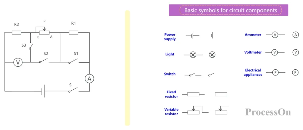
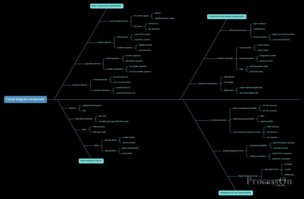
Electronic component symbols are the most basic components in circuit diagrams. Each electronic component has its own specific symbol to represent the function and characteristics of the component in the circuit. Common electronic component symbols include resistors, capacitors, inductors, diodes, transistors, integrated circuits, etc.
Connecting wires are used to connect electronic component symbols to indicate electrical connections between electronic components.
Solid Line
Indicates an electrical connection, possibly with an arrow to indicate the direction of current flow (such as a power supply output).
Cross-line processing:
No black dots at intersections: not connected (like two vertically crossing lines).
Black dots at intersections: connections (like T-junctions).
dotted line
Represents non-electrical connections, such as mechanical linkages (e.g., the physical connection of a switch), control relationships (e.g., a microcontroller pin controlling a relay).
Bus
Use thick or parallel lines to represent multiple signal lines (such as data bus and address bus) to simplify complex circuits.
The power supply is the energy source for the circuit to work, usually represented by a circle or rectangle with the voltage value and polarity of the power supply marked on it. The ground is the reference potential point in the circuit, usually represented by a triangle or ground symbol.
In circuit diagrams, power and ground symbols are usually located on the edge of the drawing or at specific locations for easy identification and connection.

Circuit diagram design principles
Labels and annotations are important components of circuit diagrams, used to explain the parameters, models, functions of electronic components, and the working principle of the circuit. Labels and annotations can be expressed in the form of text, numbers, symbols, etc., and are usually located near the electronic component symbols or in the blank space of the drawing.
For example, the resistor labeling can include information such as resistance value, power, accuracy, etc.; the capacitor labeling can include information such as capacitance value, withstand voltage, polarity, etc. At the same time, annotations can also be added to the circuit diagram to explain the working principle, special functions or precautions of the circuit.
Circuit diagrams are an important tool for electronic device design. Designers can plan the circuit structure and function of electronic devices, select appropriate electronic components, and determine the connection between them by drawing circuit diagrams. Circuit diagrams can also help designers simulate and debug circuits to ensure the performance and reliability of electronic devices.
For maintenance personnel of electronic equipment, circuit diagrams are an important basis for diagnosing and repairing faults. By analyzing circuit diagrams, maintenance personnel can understand the circuit structure and working principle of electronic equipment, determine the location and cause of the fault, and take corresponding maintenance measures.
Circuit diagrams are an important tool for teaching and learning electronic technology. Teachers can teach students the basic concepts and principles of electronic technology by explaining circuit diagrams; students can deepen their understanding and mastery of electronic technology by reading and analyzing circuit diagrams.
Professional-grade software:
Altium Designer: The industry-leading PCB design system that integrates schematic design, simulation, 3D modeling and production file output for high-end electronic product development.
OrCAD: Focuses on high-speed digital circuit design, supports signal integrity analysis and constraint-driven layout, and is often used in communication equipment development.
Lightweight tools:
ProcessOn : Supports online circuit diagram production and provides a rich vector symbol library, suitable for quick drawing of circuit diagrams.
Taking ProcessOn as an example, the following steps for making a circuit diagram are described in detail:
1. Open the ProcessOn official website, go to the personal file page, and create a flowchart.
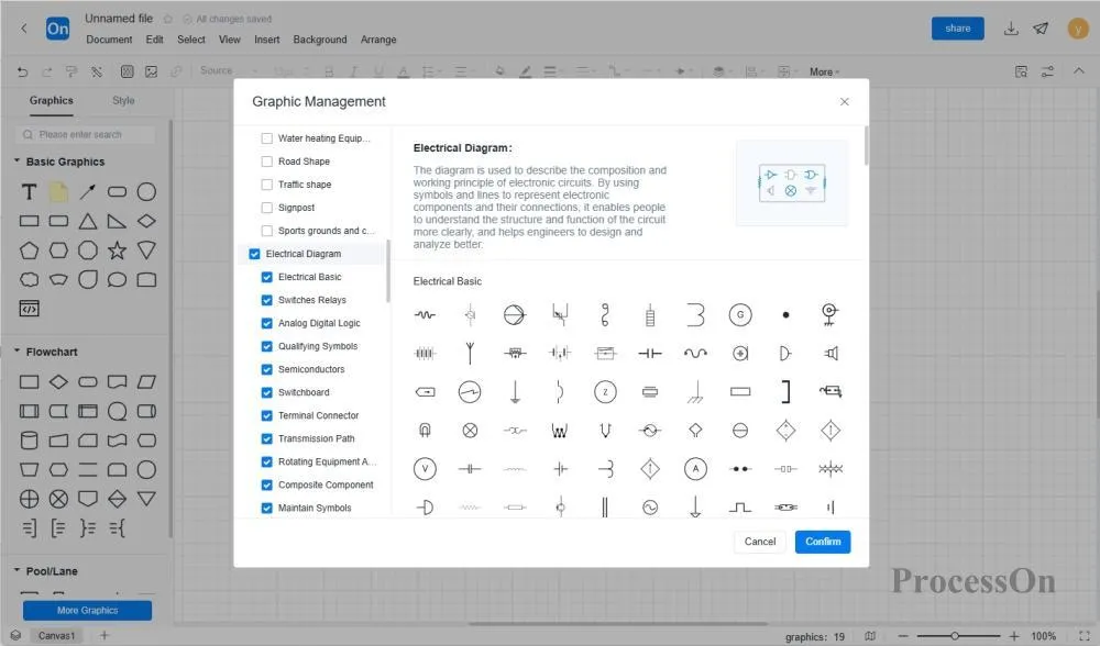
2. Click [More Graphics] in the lower left corner and select the circuit diagram.
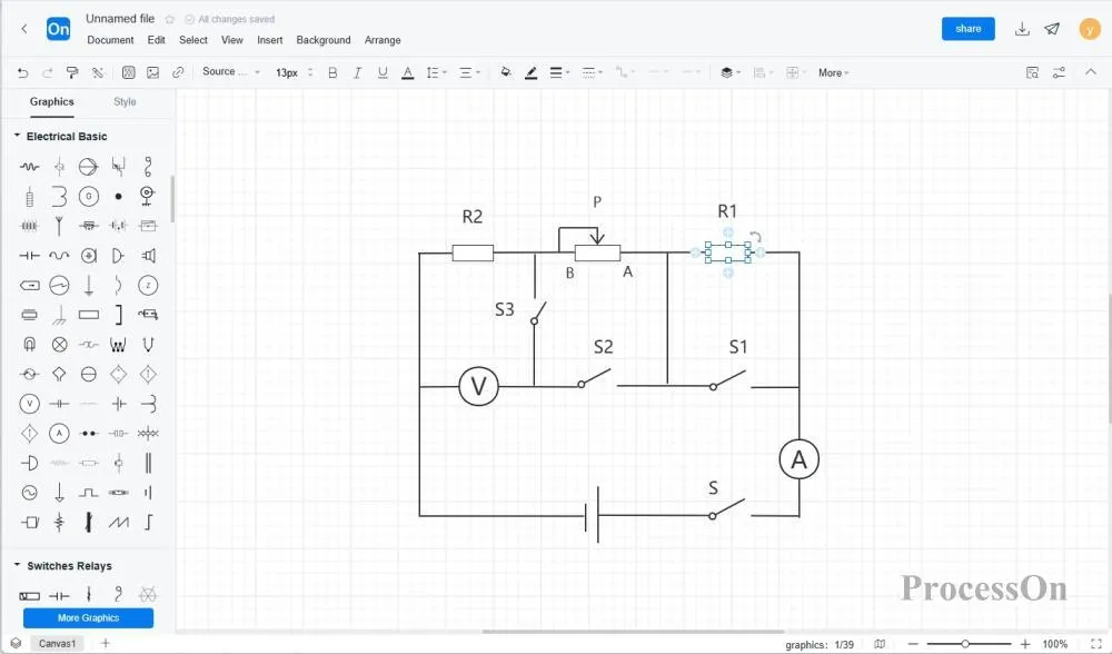
3. Drag the circuit components into the canvas according to the circuit operation order and rules, and drag the center lines of the circuit components to connect the components according to the operation process of the circuit diagram.
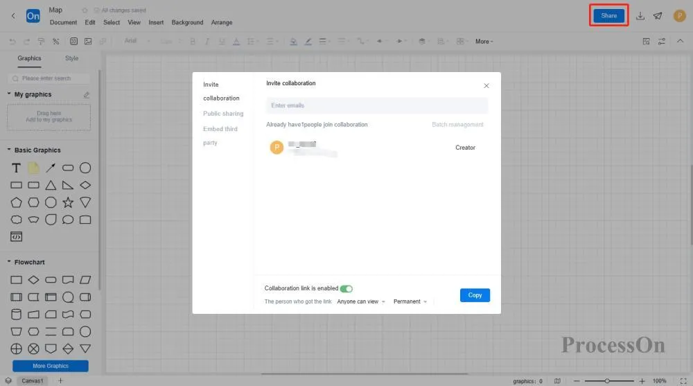
4. After the drawing is completed, it can be exported as an image or PDF format, which can be inserted into corporate documents and shared with team members. You can also directly share the circuit diagram with colleagues or customers for team members to view or edit online.
The ProcessOn template community contains a wealth of circuit diagram templates for reference, and supports copying to improve drawing efficiency. The following are some templates for sharing.
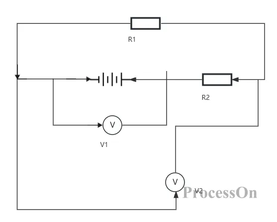
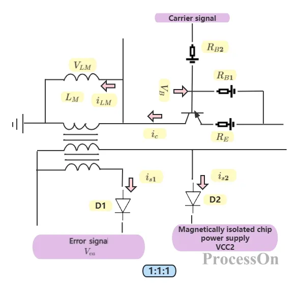
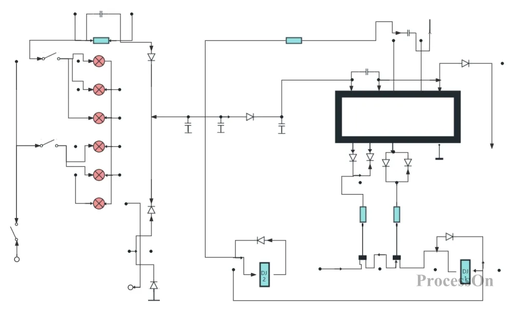
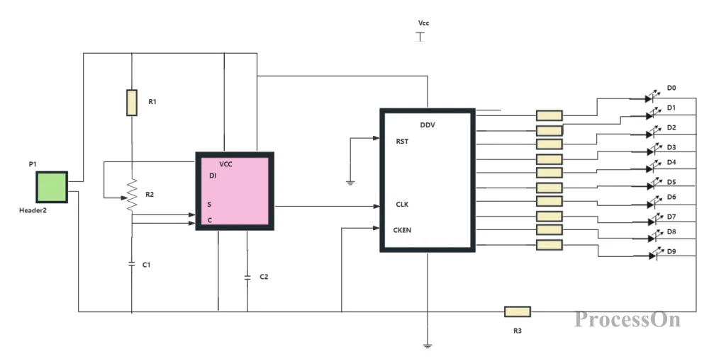
Basic Circuit Diagram
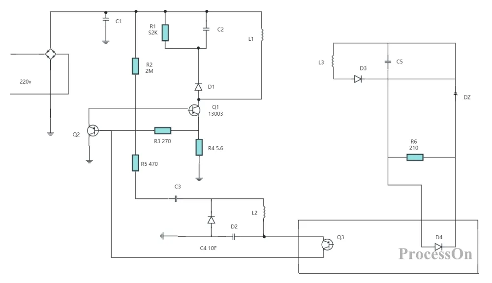
Mobile phone charging circuit diagram
ProcessOn is a very practical online drawing tool that provides us with a convenient and efficient circuit diagram drawing platform. By mastering the specific steps and methods of drawing circuit diagrams in ProcessOn, we can easily draw clear, beautiful and accurate circuit diagrams, providing strong support for the study, design and application of electronic technology. Come and use it for free !