Process Type
Graphical expression
Mind Type
Structured expression
Note Type
Efficient expression
Treemap
Bracket Diagram
Default Mode


In projects like electronics engineering and IoT development, circuit diagrams bridge the gap between design concepts and physical implementation. However, the high learning curve and localization limitations of traditional diagramming software often deter beginners. ProcessOn, a professional online diagramming platform, boasts a library of over 500 professional circuit symbols, a simple editor interface, and smooth operation, significantly reducing the learning curve for circuit diagram creation. This article, using practical examples, will teach you how to use ProcessOn to quickly create circuit diagrams that meet international standards.
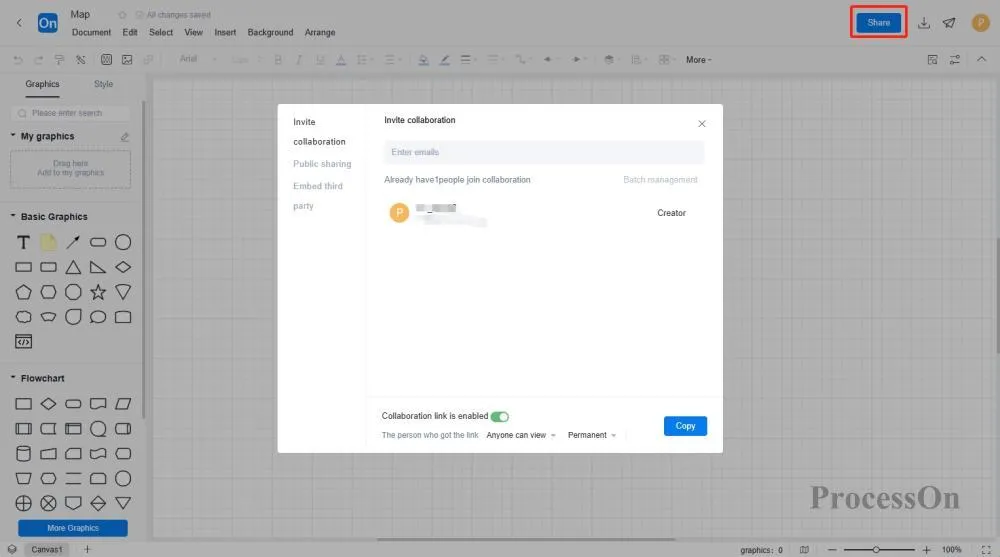
No software installation required, just open the drawing app in your browser. Team members can edit simultaneously in real time, with changes automatically saved to the cloud and support for historical version rollback. This reduces communication and collaboration costs across teams and shortens circuit design cycles.
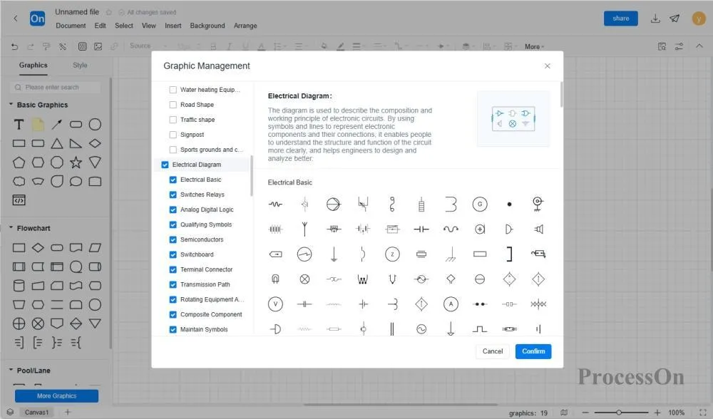
The platform has built-in 20 major categories of circuit symbols, including switching relays, semiconductor devices, integrated circuits, etc., and supports rapid calling of components through natural language descriptions (such as inputting "transistor" to automatically match symbols).
Supports importing .vsdx files generated by Visio tools and exporting them to formats such as PNG/PDF/SVG.
After logging into ProcessOn, go to the Personal Files page, click "New File" and select "Circuit Diagram." Then, in More Graphics, add the circuit diagram to the graphics library.
(1) In the icon library on the left, find the "Electronic Components" category and select the electronic component symbols you need, such as resistors, capacitors, inductors, diodes, transistors, integrated circuits, etc.
(2) Drag the selected electronic component symbol into the drawing area and place it in the appropriate position.
(3) Double-click the electronic component symbol to edit it, such as changing the component name, parameters, etc.
(4) If the circuit diagram symbols provided by the system do not meet your needs, you can also click "My Components" on the left side of the editor to create a new category, and then click Import in More to support importing symbols in formats such as png, svg, and vssx.
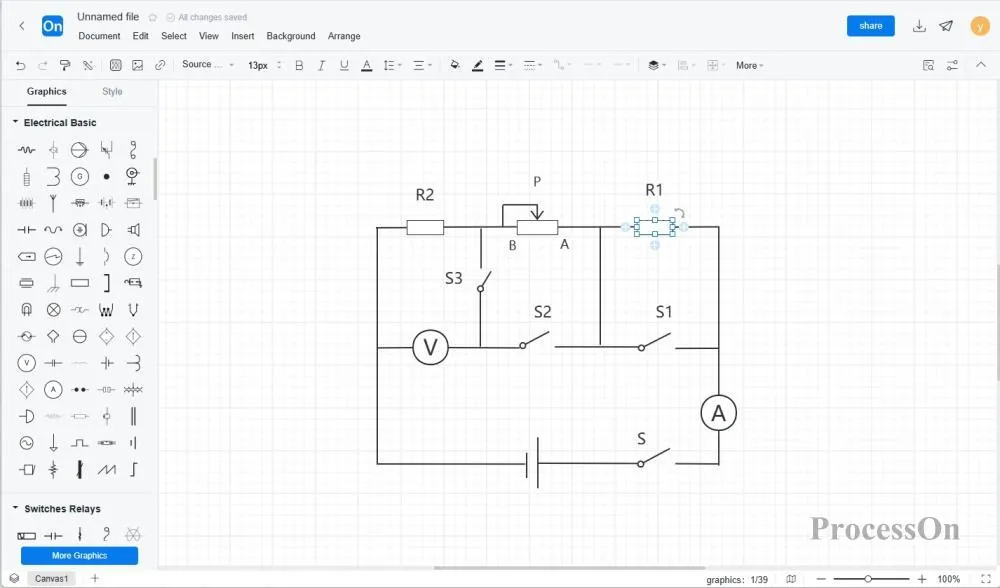
(1) Select the "Connection Line" tool in the left toolbar, click a connection point of an electronic component in the drawing area, and then drag the mouse to the connection point of another electronic component to create a connection line.
(2) Connecting lines can be straight, curved, or broken lines and can be adjusted as needed. The shape and length of a connecting line can be changed by dragging its endpoints or midpoints.
(3) Double-click the connecting line to edit it, such as changing the line color, thickness, style, etc.
(1) In the icon library on the left, find the "Power and Ground" category and select the appropriate power and ground symbols, such as battery, DC power supply, ground symbol, etc.
(2) Drag the power and ground symbols into the drawing area and place them in appropriate locations.
(3) Connect power and ground symbols to other electronic components to ensure circuit integrity.
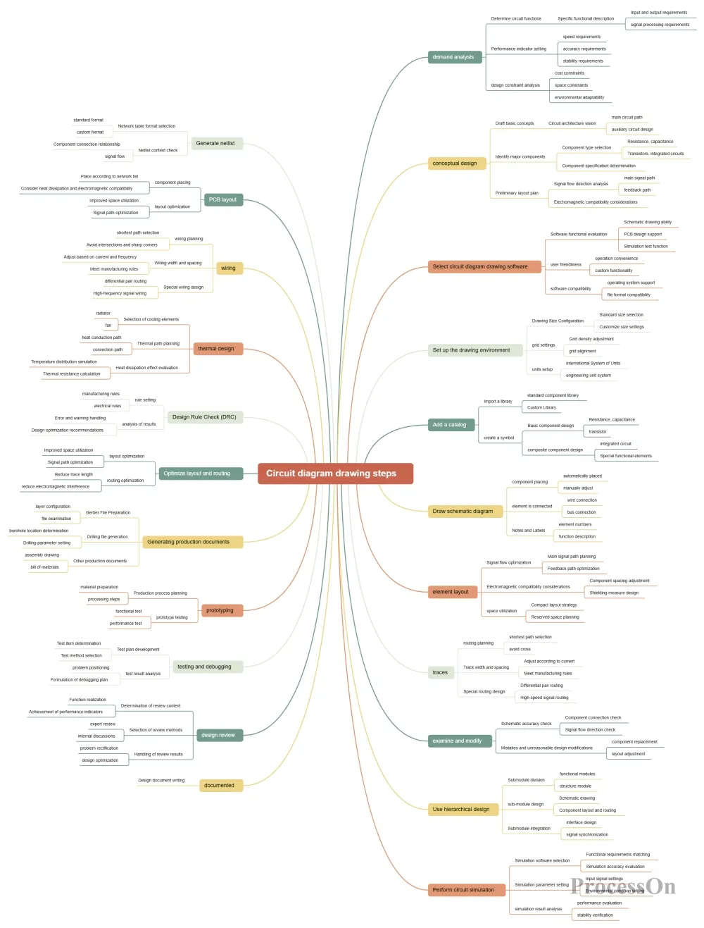
Steps for drawing a circuit diagram
(1) Double-click the canvas to add a text box.
(2) Enter annotations or notes in the text box, such as electronic component parameters, circuit function descriptions, etc.
(3) You can adjust the size and position of the text box by dragging its border, or edit it by double-clicking it, such as changing the font, color, size, etc.
(1) Adjust the color, font, size, and other styles of electronic component symbols, connecting lines, and text boxes to make the circuit diagram more beautiful and easy to read.
(2) Add decorative elements such as background color and borders to enhance the visual effect of the circuit diagram.
(3) Use tools such as alignment and distribution to adjust the position and spacing of electronic components to make the circuit diagram layout more reasonable.
(1) Carefully check the circuit diagram for correct component symbols, accurate connections, and clear markings and annotations.
(2) Optimize the circuit diagram, remove unnecessary elements, and simplify the structure. Improve the readability of the circuit diagram by merging duplicate components and optimizing the routing of connecting wires.
(3) Perform circuit simulation or actual testing to verify the correctness and performance of the circuit diagram. If any problems are found, make adjustments and modifications in a timely manner.

How to Check and Verify Circuit Diagrams
After you've finished drawing, export it as an image or PDF, which you can then insert into company documents and share with your team. You can also directly share your circuit diagram with colleagues or clients, allowing them to view or edit it online.
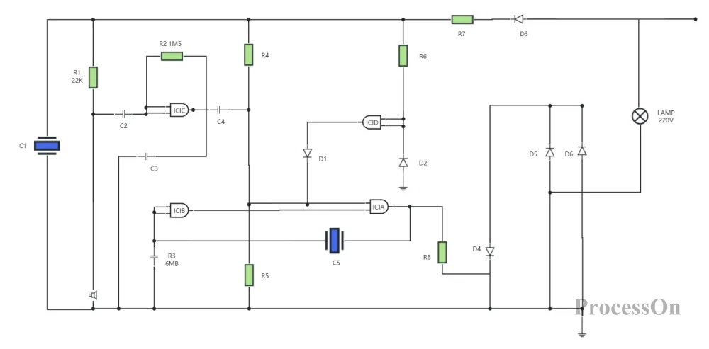
The ProcessOn template community contains a wealth of circuit diagram templates for reference, and they can be copied and reused to improve drawing efficiency. Below are some templates shared.
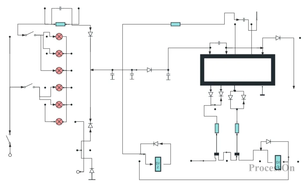
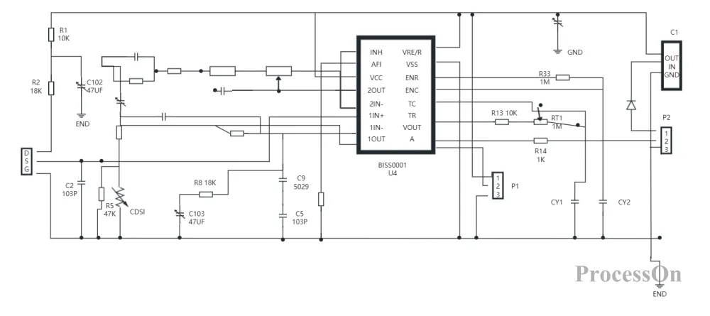

General circuit diagram mobile phone circuit
The above is a tutorial for creating circuit diagrams online using ProcessOn. Through systematic creation ideas and standardized processes, even non-professional circuit designers can quickly draw circuit diagrams that meet industry standards. ProcessOn's circuit diagram maker further lowers the barrier to entry for circuit design, allowing teams to focus on innovation rather than repetitive work.