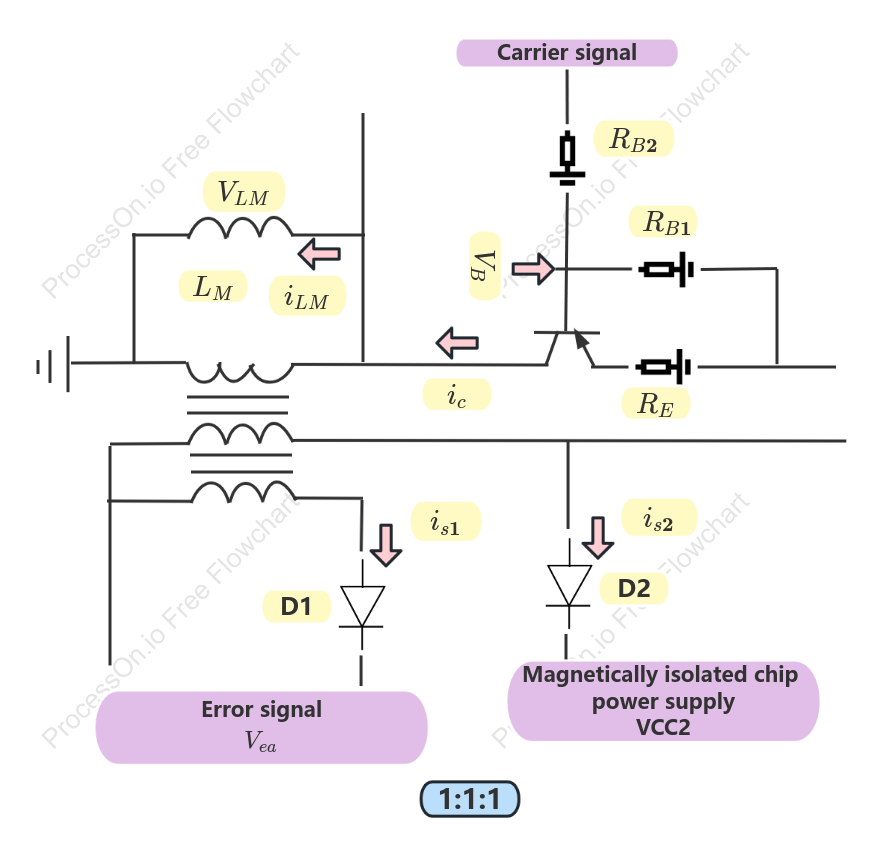

Circuit diagram of three-winding transformer
2 Report
The circuit diagram of a three-winding transformer provides a detailed representation of the transformer's components and their interactions. This diagram highlights key elements such as the 1:1:1 winding ratio, which is crucial for maintaining balance and efficiency in power distribution. It also features a magnetically isolated chip power supply (VCC2) that ensures safety and reliability. Additionally, the diagram includes a carrier signal and error signal pathways, essential for monitoring and controlling the transformer's performance. This comprehensive schematic serves as an invaluable resource for understanding the intricate workings of a three-winding transformer.
Related Recommendations
Other works by the author
Outline/Content
See more
1:1:1
D2
Magnetically isolated chip power supplyVCC2
Carrier signal
Error signal
D1


Collect

0 Comments
Next Page