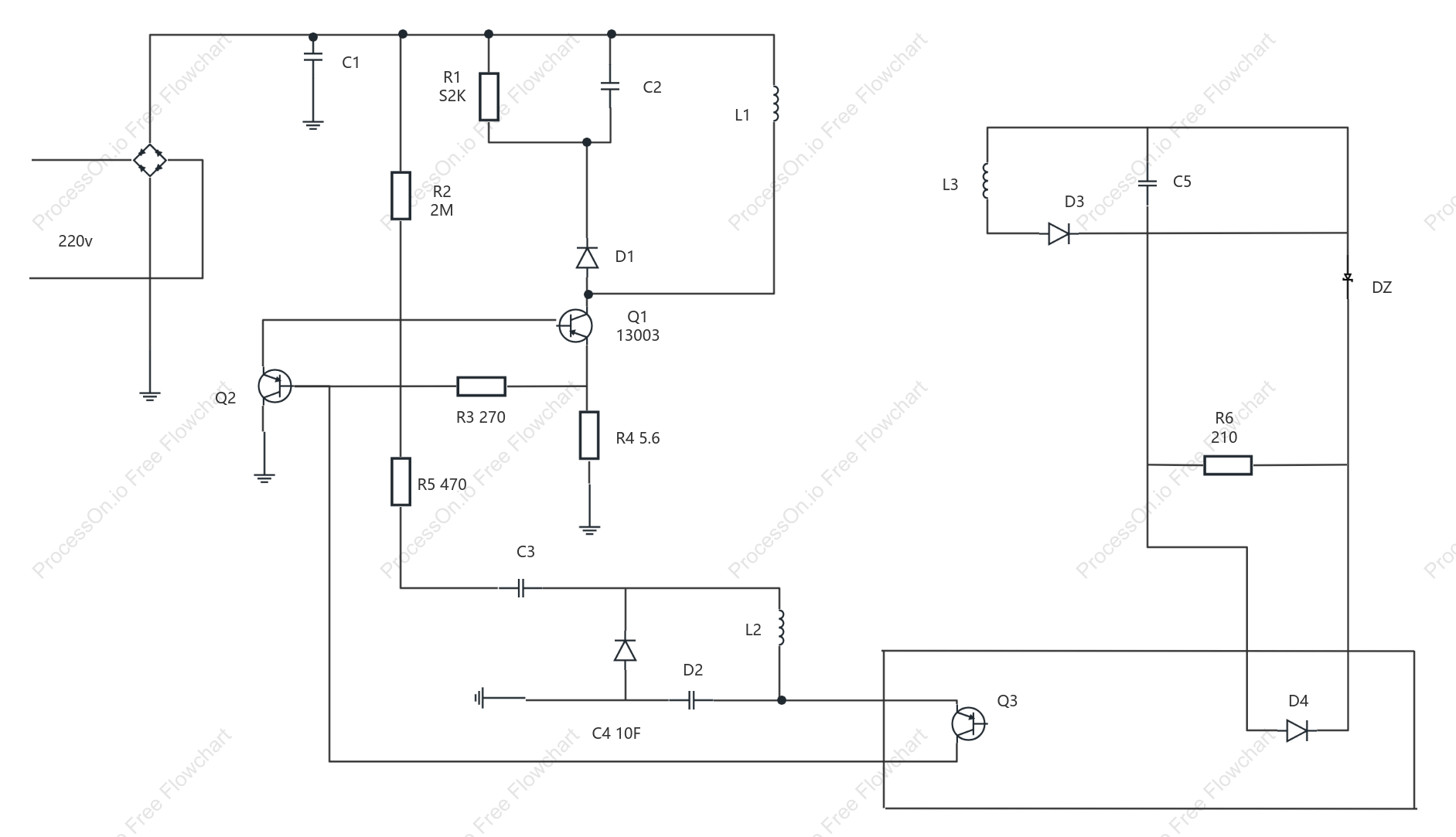

Mobile phone charging circuit diagram
0 Report
This is a mobile phone charging circuit diagram, designed to illustrate the components and connections involved in the charging process. The diagram includes elements such as diodes (D1, D2, D3, D4), resistors (R3, R4, R5, R6), capacitors (C1, C2, C3, C4, C5), inductors (L1, L2, L3), and transistors (Q1, Q2, Q3). It operates on a 220V power supply and integrates components like a Zener diode (DZ) for voltage regulation. This circuit diagram is intended to help understand the flow and control of electrical current in mobile phone charging systems.
Related Recommendations
Other works by the author
Outline/Content
See more
D2
R22M
D4
R3 270
DZ
R1S2K
C1
L3
R4 5.6
C5
Q2
Q113003
C2
D1
L1
R5 470
220v
Q3
D3
C4 10F
R6210
C3
L2


Collect

Collect

0 Comments
Next Page