Process Type
Graphical expression
Mind Type
Structured expression
Note Type
Efficient expression
Treemap
Bracket Diagram
Default Mode


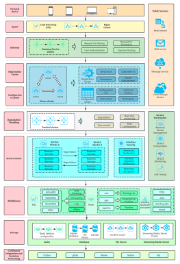
As the wave of digitalization sweeps the world, the network has become the invisible vein that supports the operation of modern society. The network topology diagram is the "gene map" that interprets this huge system. It transforms the abstract network structure into an analyzable and manageable visual model through intuitive graphic language. Today, we mainly introduce the common structure of the network topology diagram - bus topology.
Bus topology is a linear network structure in which all devices are connected through a shared backbone cable (called a "bus"). Data is transmitted bidirectionally on the bus in a broadcast mode. Information sent by any device will be received by other devices on the bus, but only the target device will process the information.
Just like a highway, all vehicles (equipment) travel on the same lane (bus), and vehicles with different destinations need to judge for themselves whether they need to leave.
1. Simple structure and low cost
Only one backbone cable and a few connectors are required, and the hardware cost is significantly lower than topologies such as star and ring. Suitable for scenarios with a small number of devices and limited budget.
2. Flexible expansion, but bus dependent
New devices can be added by simply plugging them into any location on the bus without complicated configuration. However, a bus failure can cause the entire network to fail, and performance can drop dramatically when there are too many devices.
3. Conflicts and broadcast issues
All devices share bandwidth, and data collisions are prone to occur under high load (needs to rely on CSMA/CD and other protocols for coordination). The risk of broadcast storms is low, but privacy is weak.
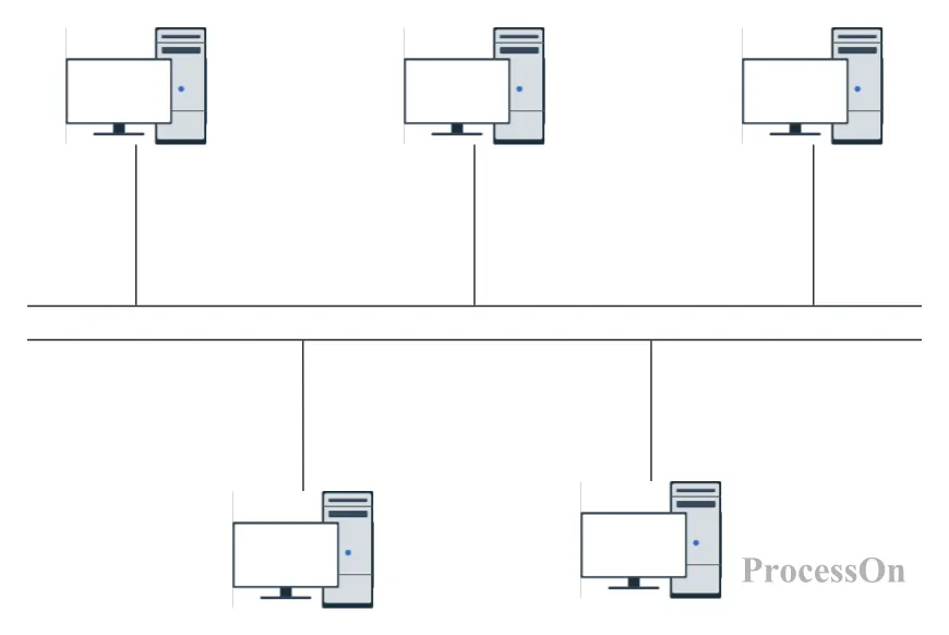
Bus: As a shared transmission medium, it is usually a single cable (such as coaxial cable or twisted pair), and all nodes are connected to this bus through a hardware interface. The bus is responsible for transmitting data between nodes in a broadcast mode, that is, data sent by a node can be received by all nodes on the bus.
Nodes: Network devices such as computers, servers, and printers. Each node is connected to the bus through a corresponding hardware interface (such as a network interface card). Nodes have the function of sending and receiving data, and can identify the target address to decide whether to process the received data.
Terminators: Devices installed at both ends of the bus for impedance matching, absorbing signal energy at the end of the transmission, and preventing signal reflection from causing interference. This is critical to maintaining signal integrity.
Connectors and taps: Connectors are used to physically connect nodes to the bus, while taps are branching points on the bus that allow nodes to connect to the trunk cable. These components ensure that signals can be transmitted effectively, and the number and spacing of taps must be paid attention to to avoid signal attenuation.
| Dimensions | Bus topology | Star topology |
| Structure | Linear shared bus, high risk of single point failure | Centralized hub/switch, single point failure controllable |
| Reliability | If the bus breaks, the entire network will be paralyzed | Central node failure only affects local |
| Scalability | Simple but limited by bus length and number of devices | Flexible, the central node supports a large number of branches |
| Cost | Low (only backbone cable required) | Higher (needs central equipment and more cables) |
| Applicable scenarios | Small temporary networks, laboratories | Enterprise-level network, data center |
Case 1: Early Ethernet (10Base2/10Base5)
Scenario: Small office networks in the 1980s and 1990s.
Implementation: The bus is constructed through coaxial cables, and the devices are connected with T-type connectors and terminated with 50Ω resistors.
Problem: As the number of devices increased, the collision domain expanded, resulting in performance degradation, and it was eventually replaced by star Ethernet.
Case 2: Industrial control systems (such as SCADA)
Scenario: Some industrial environments still use simplified bus topologies (such as the RS-485 bus).
Advantages: Strong anti-interference ability, suitable for short-distance, low-rate device communications.
Risk: The bus length and terminal matching need to be strictly designed, otherwise signal reflection may occur.
ProcessOn is an online drawing tool that supports drawing various types of network topology diagrams, provides a large number of network topology diagram templates, and supports multi-person online collaborative editing.
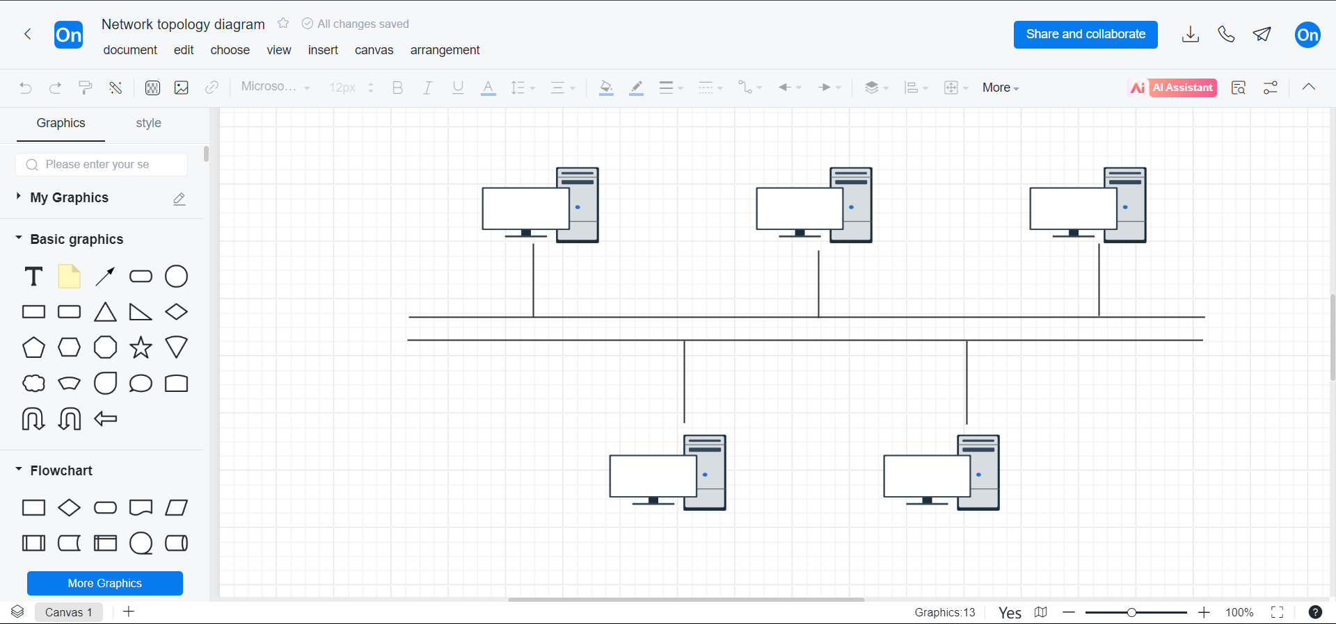
1. Log in to ProcessOn , go to the Personal Files page, and select Create New Flowchart.
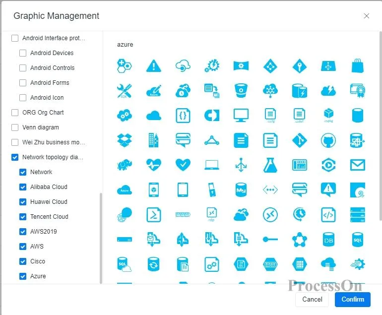
2. Click "More Graphics" in the lower left corner and select the network topology icon type according to enterprise needs.
3. Drag device icons (computers, servers, etc.) to the canvas and connect them with bus symbols. Add descriptions such as terminal resistors, connector types, etc., and use colors to distinguish different device roles.
4. completing the topology map , click the "Export" button in the upper right corner of the page, select the appropriate export format (such as PNG, JPEG, PDF, etc.), and save the topology map to your local computer. You can also click the "Share" button to generate a sharing link to share the map with colleagues or customers .
The following are some bus topology diagram templates shared in the ProcessOn template community .
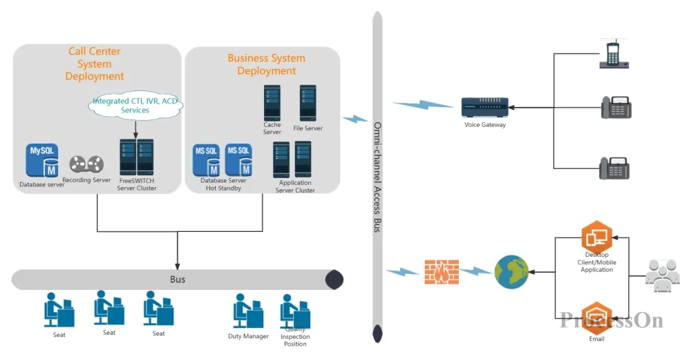
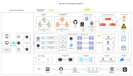
System network topology diagram
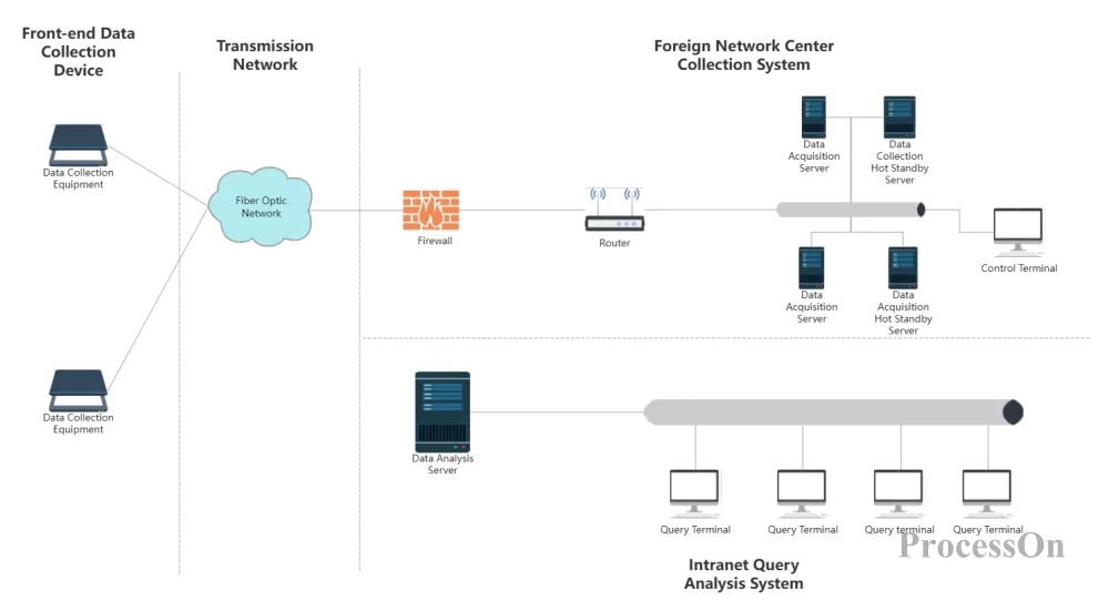
Dedicated network topology diagram - bus type
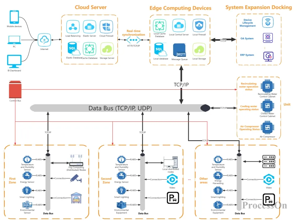
Smart Park System Network Topology
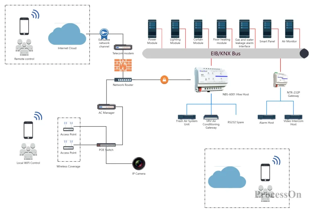
Smart Home System Topology - Bus Topology
Although bus topology is no longer the mainstream choice for modern networks, its "minimalist design" concept is still worth learning from. Whether you are drawing industrial control diagrams, teaching presentations, or optimizing temporary network solutions, a flexible topology tool can make complex logic clear at a glance.