Process Type
Graphical expression
Mind Type
Structured expression
Note Type
Efficient expression
Treemap
Bracket Diagram
Default Mode


Series and parallel circuit diagrams are fundamental to electronic design and serve as simplified models for understanding complex systems, such as power grids and neural networks. By mastering their core characteristics and drawing techniques, engineers can efficiently navigate the entire process from proof of concept to product implementation. This article will provide an introduction to series and parallel circuits.
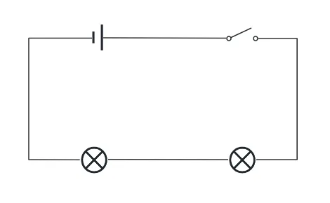
The current originates from the positive terminal of the power supply , flows through each component (such as a resistor, light bulb, motor, etc.) in sequence, and finally returns to the negative terminal of the power supply, forming a single closed circuit structure. The current has only one path to flow, and the components are connected in series.
Conservation of current: The current through each component is equal (I=I1=I2=...=In).
Voltage superposition: The total voltage is equal to the sum of the partial voltages of each component (U=U1+U2+...+Un).
Fault chain reaction: A break in any component will cause the entire circuit to fail.
Uneven voltage distribution risk: If component resistances vary significantly, some components may experience overvoltage (e.g., when light bulbs of different wattages are connected in series, the lower-wattage bulb is more likely to burn out).
Fault sensitivity: Failure of a single component can cause overall paralysis, and there is a lack of redundant design.
Power limitation: The total power is limited by the minimum rated component (P=I2 ⋅ R), so component parameters must be selected carefully.
High voltage requirements
Battery packs connected in series: The flashlight uses two 1.5V dry batteries connected in series to obtain a total voltage of 3V.
Electric vehicle power: Lithium battery packs are connected in series to increase voltage (for example, a 48V electric vehicle is made up of 16 3V batteries connected in series).
Current Limitation and Protection
LED drive circuit: The series resistor limits the current to a safe range (such as 20mA) to prevent the LED from being damaged by overload.
Voltage sampling: In a voltage monitoring circuit, a series resistor converts a high voltage into a low voltage signal that can be read by an ADC.
Special function implementation
Delay circuit: Connect a large-capacity capacitor and a resistor in series, and use the charging time constant (τ=RC) to achieve a delay effect.
Temperature sensing: Thermistor (NTC) is connected in series in the circuit and reflects temperature changes through voltage changes.
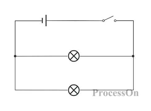
A circuit structure in which multiple components are connected together at both the head and tail ends to form multiple independent branches. This allows current to flow through different paths, placing the components in parallel.
Constant voltage: The voltage at both ends of each branch is equal (U=U1=U2=...=Un).
Current distribution: The total current is equal to the sum of the currents in each branch (I=I1+I2+...+In).
Independent operation: A circuit breaker in any branch does not affect other branches (e.g. light bulbs in a home lighting system do not interfere with each other).
Resistance matching risk: If the branch resistance difference is too large, it may cause excessive current in some branches (for example, when connecting light bulbs of different wattages in parallel, the high-wattage light bulb may be overloaded).
Wiring complexity: As the number of components increases, the number of wire connection points increases, which may cause poor contact or short circuit problems.
Uneven power distribution: The total power is limited by the power supply capacity (P = U⋅I). Ensure that the power supply can provide sufficient current.
Home electrical system
Parallel design: All electrical appliances (such as refrigerators, air conditioners, and TVs) are connected in parallel to the 220V power supply, can be switched on and off independently, and the voltage is stable.
Advantage: Avoid the problem of a single appliance failure in a series connection causing a power outage for the entire home.
Power supply redundancy design
Parallel connection of batteries: Connecting multiple identical batteries in parallel can increase the total capacity (battery life) while keeping the voltage constant (for example, if two 3.7V lithium batteries are connected in parallel, the output remains 3.7V, but the capacity is doubled).
Application: UAV battery pack, mobile power supply.
Current expansion and current splitting
High current load: Share high current by connecting multiple low-power resistors in parallel (such as shunt resistors in power amplifiers).
Current sampling: Connect a small resistor in series with the parallel branch and indirectly obtain the total current by measuring the voltage drop (such as in motor drive circuits).
1. ProcessOn is a professional diagramming tool that supports creating circuit diagrams online. First, go to the ProcessOn file page and create a circuit diagram.
2. Drag the power supply, switch, electronic components and other components in the circuit diagram to the center of the canvas, and drag the center line of the circuit components to connect the components according to the operation process of the circuit diagram.
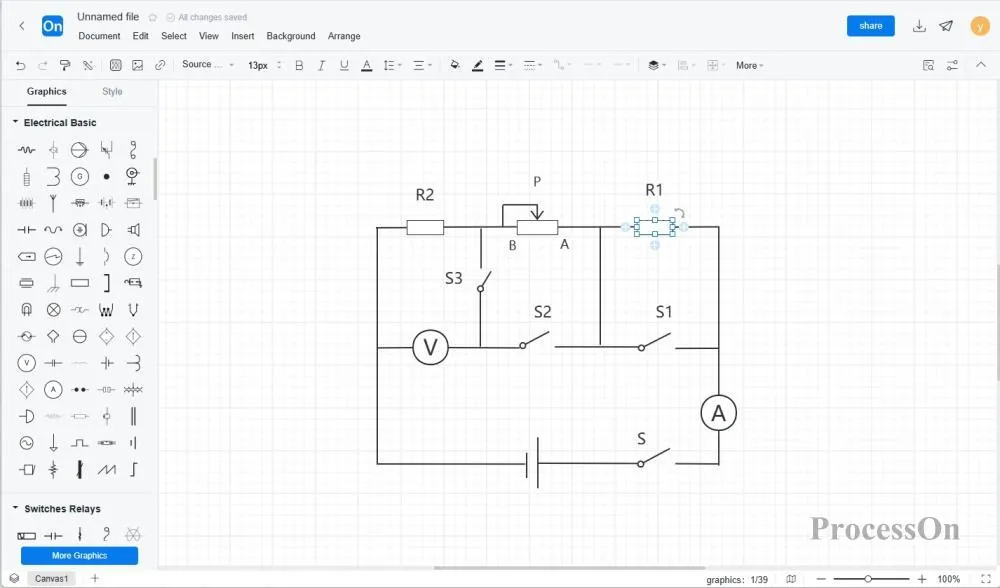
3. After the circuit diagram is drawn, check whether the electronic component symbols and connection sequence are correct .
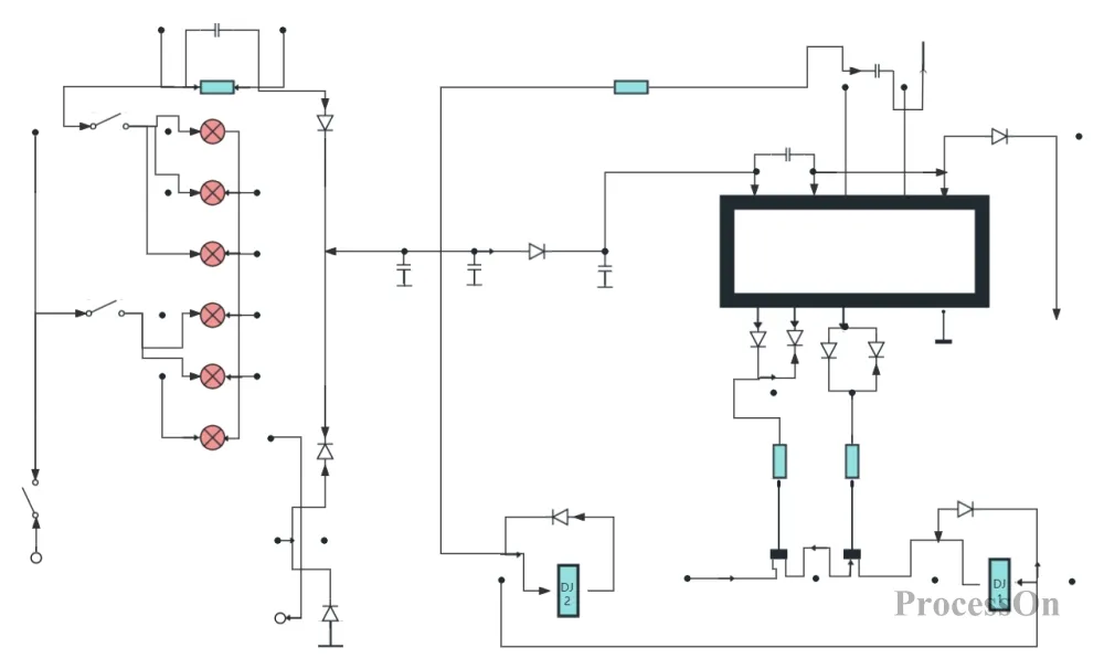
The ProcessOn template community contains a wealth of circuit diagram templates for reference, and supports copying and reuse to improve drawing efficiency.

Automotive Electrical Equipment Circuit Diagram

Two-winding transformer circuit diagram

General circuit diagram mobile phone circuit
Series circuits, with their simple structure and well-defined physical laws, play a key role in scenarios requiring voltage division, current limiting, or high voltage. Parallel circuits, with their voltage stability, fault isolation, and scalable current, have also become an indispensable foundational structure in modern electronic systems. In practical circuits, series and parallel connections are often used in combination. Understanding their principles and design key points is crucial for better analysis of complex circuits.