

Power Supply and Energy Storage Process Flowchart
3 Report
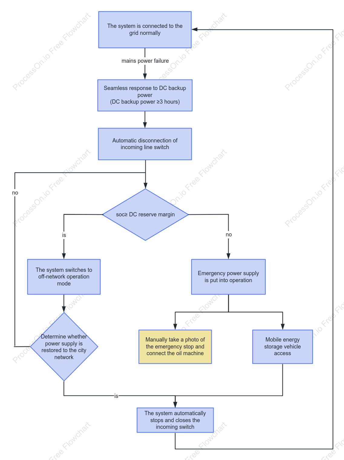
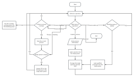
This is an emergency switching flowchart for a power supply and energy storage system. The system begins with normal grid-tied operation; upon a mains power outage, it switches to DC battery backup (providing approximately 2–3 hours of power) and automatically disconnects the mains input. The system then assesses the battery state of charge (SOC): if the charge is sufficient, it shifts to off-grid mode while continuously monitoring for the restoration of mains power; if the charge is insufficient, it initiates emergency power measures (such as a manual emergency shutdown followed by a switch to a diesel generator or connection to a mobile energy storage vehicle). Finally, the system performs an automatic shutdown and circuit breaker closure, awaiting the restoration of mains power to return to normal grid-tied operation, thereby establishing a complete closed-loop protection mechanism.
Related Recommendations
Other works by the author
Outline/Content
See more
Automatic disconnection of incoming line switch
Mobile energy storage vehicle access
is
Emergency power supply is put into operation
Manually take a photo of the emergency stop and connect the oil machine
no
The system switches to off-network operation mode
Determine whether power supply is restored to the city network
The system automatically stops and closes the incoming switch
Seamless response to DC backup power(DC backup power ≥3 hours)
The system is connected to the grid normally
soc≥ DC reserve margin
mains power failure
Collect
Collect
Collect
Collect

0 Comments
Next Page