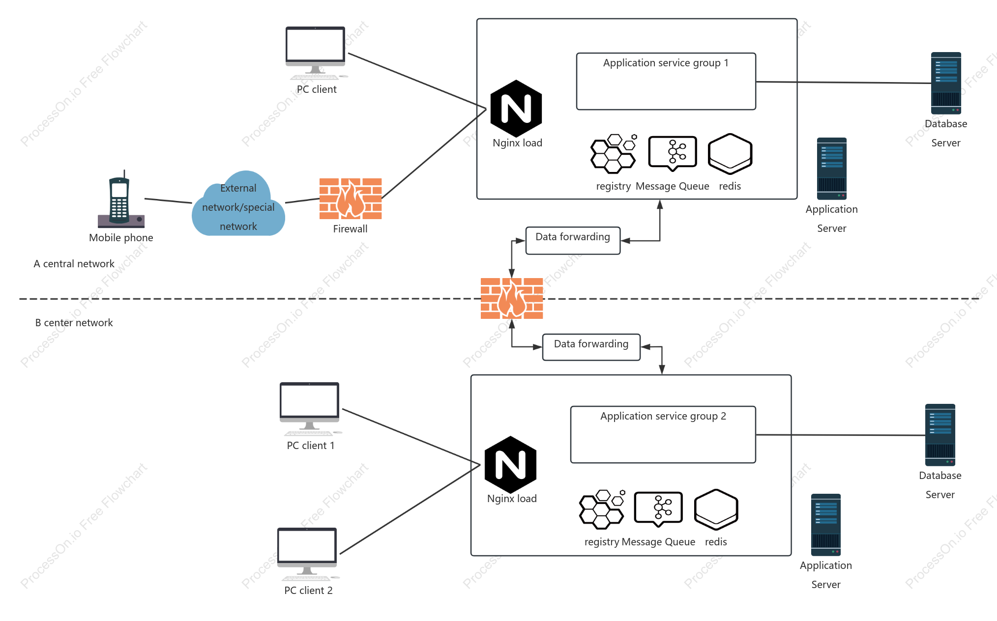

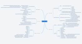
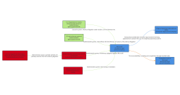
Interconnected deployment topology diagram of sub-centers
1 Report
This is an interconnected deployment topology diagram of sub-centers, designed to illustrate the network architecture and data flow between various components. The diagram highlights critical elements such as the B center network, application servers, PC clients, and firewalls. It includes data forwarding mechanisms, mobile phone access, application service groups, registries, Redis, database servers, and message queues. Additionally, it depicts the role of Nginx load balancing and the integration with external or special networks. By visualizing these connections, the diagram provides a comprehensive overview of the system's infrastructure and communication pathways.
Related Recommendations
Other works by the author
Outline/Content
See more
B center network
Application Server
PC client 1
Firewall
Data forwarding
Mobile phone
Application service group 2
registry
redis
Database Server
External network/special network
Message Queue
PC client
Nginx load
Application service group 1
A central network
PC client 2
Collect
Collect
Collect

0 Comments
Next Page