
Smart home system topology - bus topology
0 Report
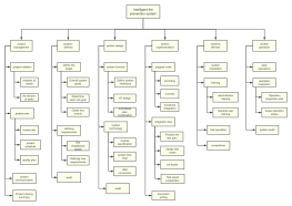
This flowchart illustrates the smart home system topology using a bus topology framework. It highlights the integration of various components such as the Access Point, AC Manager, Alarm Host, and NBS-6001 Hive Host, all interconnected through an exclusive network channel. Key modules include the Floor Heating Module, VRV Air Conditioning Gateway, and Lighting Module, ensuring comprehensive home automation. The system supports robust connectivity with elements like the Internet Cloud, Telecom Modem, and Wireless Coverage. Safety and convenience are enhanced with features like the Gas and Water Leakage Alarm Interface, IP Camera, and Video Intercom Host, all manageable via remote and local WiFi control.
Related Recommendations
Other works by the author
Outline/Content
See more
Access Point
AC Manager
Alarm Host
NBS-6001 Hive Host
RS232 Spare
NTR-232P Gateway
Exclusive network channel
Floor heating module
VRV Air Conditioning Gateway
Internet Cloud
Power Module
Curtain Module
Gas and water leakage alarm interface
Lighting Module
Wireless Coverage
IP Camera
Smart Panel
Telecom modem
EIB/KNX Bus
Remote control
Local WiFi Control
Air Monitor
POE Switch
Network Router
Fresh Air System Unit
Video Intercom Host
Collect
Collect
Collect
Collect
Collect
Collect

0 Comments
Next Page