
Tree Topology
3 Report
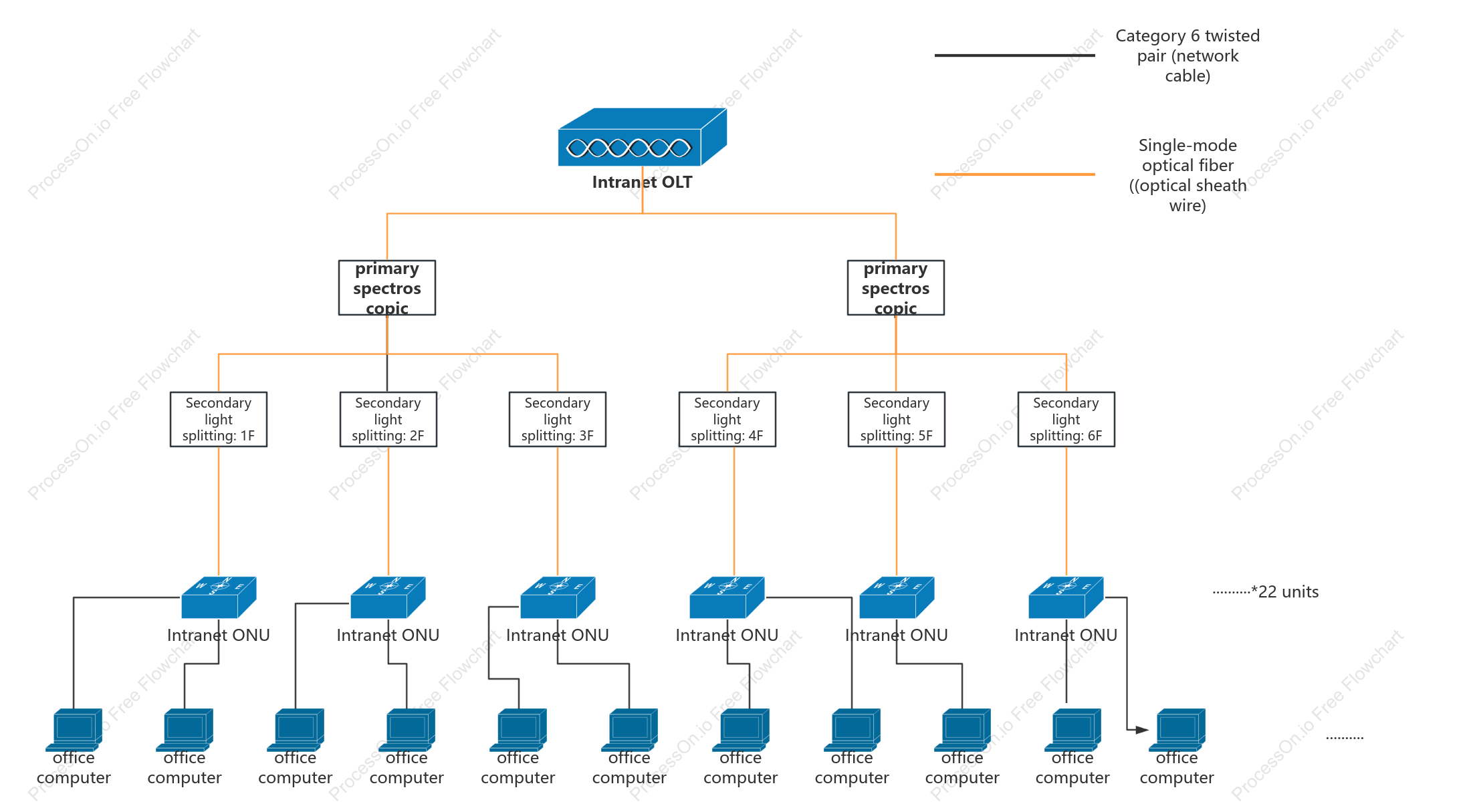
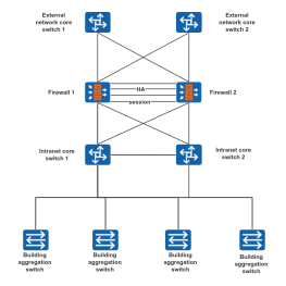
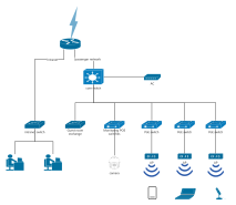
This flowchart illustrates the network structure of a tree topology, detailing the distribution of connections across multiple floors. It highlights the use of secondary light splitting on floors 1 through 6, connecting office computers and Intranet ONUs via Category 6 twisted pair cables and single-mode optical fibers. The diagram emphasizes the primary and secondary spectroscopic connections, ensuring efficient data distribution throughout the building. This network setup is designed to optimize communication and data flow, providing a robust infrastructure for office operations.
Related Recommendations
Other works by the author
Outline/Content
See more
Secondary light splitting: 1F
office computer
Secondary light splitting: 5F
Intranet ONU
Category 6 twisted pair (network cable)
··········*22 units
··········
primary spectroscopic
Single-mode optical fiber ((optical sheath wire)
Secondary light splitting: 4F
Secondary light splitting: 3F
Secondary light splitting: 2F
Intranet OLT
Secondary light splitting: 6F
Collect

Collect
Collect
Collect
Collect

0 Comments
Next Page