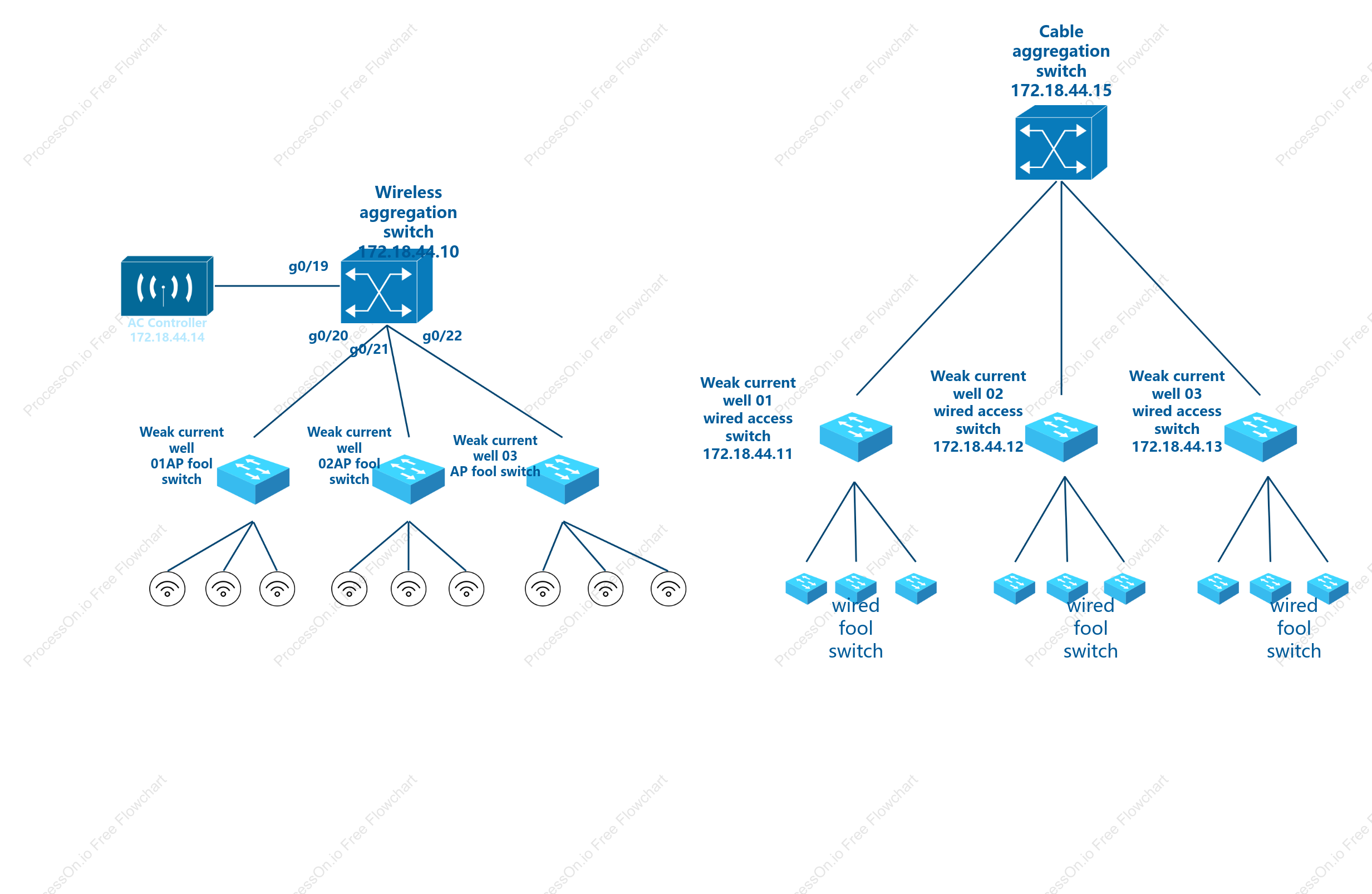

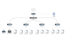
Tree Topology
7 Report
This flowchart illustrates the {Tree Topology} of a network system, detailing the interconnections between various switches and controllers. It includes wireless aggregation switches, wired access switches, and an AC controller, each identified by unique IP addresses such as 172.18.44.11 and 172.18.44.14. The diagram highlights connections at specific ports like g0/19, g0/20, g0/21, and g0/22, emphasizing the structured layout of the network's weak current wells and cable aggregation switch. This visual representation is designed to facilitate understanding of the network's architecture and its component interactions.
Related Recommendations
Other works by the author
Outline/Content
See more
Wireless aggregation switch172.18.44.10
wired fool switch
g0/19
Weak current well 01wired access switch172.18.44.11
Weak current well02AP fool switch
Cable aggregation switch172.18.44.15
g0/20
Weak current well01AP fool switch
Weak current well 02wired access switch172.18.44.12
AC Controller 172.18.44.14
Weak current well 03wired access switch172.18.44.13
Weak current well 03AP fool switch
g0/21
g0/22
Collect

Collect
Collect
Collect
Collect
Collect

0 Comments
Next Page