

Product Software Block Diagram
0 Report
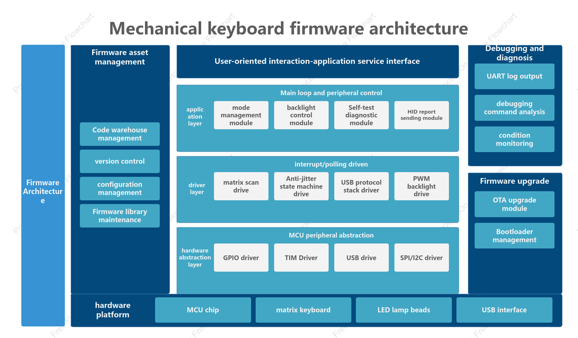
This diagram illustrates the firmware architecture of a mechanical keyboard, organized by functional logic into horizontal software layers and vertical support systems. The horizontal layers, arranged from bottom to top, comprise the hardware platform (MCU, keyboard matrix, etc.), the hardware abstraction layer (drivers for GPIO, USB, SPI/I2C, etc.), the driver layer (matrix scanning, debouncing, USB protocol, PWM backlighting, etc.), and the application layer (mode management, backlight control, self-test diagnostics, etc.), with user-facing application service interfaces at the very top. Flanking these on both sides are support modules—such as firmware asset management, debugging and diagnostics (UART logging, command parsing), and firmware updates (OTA, bootloader management)—creating a complete, modular, and maintainable embedded software system.
Related Recommendations
Other works by the author
Outline/Content
See more
HID report sending module
Firmware library maintenance
Firmware Architecture
hardware platform
configuration management
MCU chip
application layer
LED lamp beads
GPIO driver
condition monitoring
hardware abstraction layer
USB interface
USB protocol stack driver
matrix scan drive
TIM Driver
Anti-jitter state machine drive
PWM backlight drive
Mechanical keyboard firmware architecture
Code warehouse management
Debugging and diagnosis
mode management module
version control
Bootloader management
matrix keyboard
Firmware asset management
debugging command analysis
driver layer
OTA upgrade module
Self-test diagnostic module
Main loop and peripheral control
USB drive
MCU peripheral abstraction
Firmware upgrade
backlight control module
UART log output
SPI/I2C driver
User-oriented interaction-application service interface
interrupt/polling driven
Collect
Collect
Collect
Collect

0 Comments
Next Page