
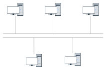
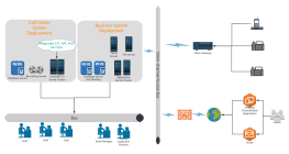
Smart campus system bus topology
1 Report
This flowchart illustrates the Smart Campus System Bus Topology, detailing the integration of various technological components and their connections. Key elements include RJ485 connections for data transmission, local and cloud servers for data management, and distributed nodes for fog computing. The system incorporates smart lighting, energy sensors, and environmental equipment to optimize campus operations. It also features device lifecycle management, local cache databases, and elastic servers for efficient resource utilization. The topology supports real-time synchronization and system expansion, ensuring seamless operation across zones and areas, thereby enhancing the campus's technological infrastructure.
Related Recommendations
Other works by the author
Outline/Content
See more
RJ485
Load Balancing
Local Firewall
Chilled Water Control Cabinet
Air Compressor
OA System
First Zone
Local distributed nodes
Video
…
Connection
Data Bus
Smart Lighting
Cloud Server
TCP/IP
Device Lifecycle Management
Local Storage
Fog Computing (Distributed) Nodes
Unit
Local Cache Database
Elastic Server
PC
Energy Sensor
Local database
Storage Server
Temperature and Humidity Sensor
Edge Computing Devices
Cache Database
Recirculating Water Control Cabinet
Local Central Server
Internet
Cloud Firewall
HTTP/TCP/IP
Second Zone
System Expansion Docking
Control Bus
Real-time synchronization
Environmental Equipment
Air Compressor Operating Status
Mobile devices
Energy Harvesting
ERP System
Other areas
Elastic Database
Environmental Sensor
BI Dashboard
Cooling water operating status
Recirculating water operation status
Message Queue
Collect
Collect
Collect
Collect
Collect
Collect
Collect
Collect

0 Comments
Next Page