
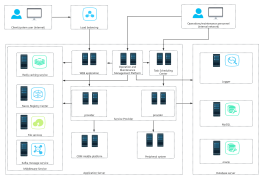
Hardware topology diagram based on front-end and database
1 Report
This hardware topology diagram illustrates the intricate relationships between front-end components and the database infrastructure. Key elements include Redis for distributed locking and persistence, utilizing both RDB and AOF methods. The architecture features multiple servers, such as Server 1 and Server 4, supporting modules like service modules and a Bloom Filter. NGINX is employed for reverse proxy and load balancing, ensuring efficient traffic management. The diagram also highlights the use of buffers like aof_buf and aof_rewrite_buf, emphasizing the importance of data integrity and performance. This comprehensive layout is essential for understanding the system's operational dynamics.
Related Recommendations
Other works by the author
Outline/Content
See more
redis
Distributed lock
RDB persistence
binary
Server 3
Output:
NGINX
Supplementary rewrite omission
Final document
Service Module 2
Server 1
Bloom Filter
Client
Server 4
Server 2
Output:
Database
Service Module 1
Rewrite
Reverse Proxy
aof_buf buffer
aof_rewrite_buf
Gateway
Load balancing
Disk
AOF persistence
disk
Collect
Collect
Collect
Collect
Collect
Collect
Collect

0 Comments
Next Page